
Data Sheet


Page
21
Cat. Nº: ABOX-104-001-71
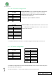
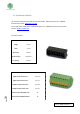
8.3 RS- 232 Switch configuration
RS-232 TOP ZONE: In order to enable the RS-232 protocol the
TOP ZONE must be configured as it is shown in the table.
Although the switch name only is referenced to RS-485 it is
also the same for the RS-232.
Having this set up, the R7 & R8 are disabled.
RS-232 LEFT ZONE: As both RS-232 & RS-485 can’t work at the same
time, the RE-RS485 and DE-RS485 have to be in OFF mode, so this
enables the I0.4, I0.5 inputs.
* To enable the RS-232 communication it is needed to configure also the jumpers, see Section 10
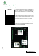
8.4 I2C Switch configuration
To enable I2C configuration the switches SCL/R5 & SDA/I0.0 must be set to ON. As they are in
ON mode R5 & I0.0 are disabled.
The switches marked as “ – “ don’t interfere with the I2C communication protocol.
TOP ZONE
SWITCH
MODE
DI - RS-485
ON
R8
OFF
DO - RS-485
ON
R7
OFF
LEFT ZONE
SWITCH
MODE
NC
-
H/F
-
SCL/R5
-
SDA/I0.0
-
RE-RS485
OFF
I0.4
ON
DE-RS485
OFF
I0.5
ON
TOP ZONE
SWITCH
MODE
DI - RS-485
-
R8
-
DO - RS-485
-
R7
-
LEFT ZONE
SWITCH
MODE
NC
-
H/F
-
SCL/R5
ON
SDA/I0.0
ON
RE-RS485
-
I0.4
-
DE-RS485
-
I0.5
-