
Data Sheet

Page
20
Cat. Nº: ABOX-104-001-71
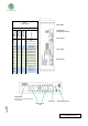
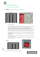
1. D1 – RS-485: If this switch is ON, the R8 switch must be set to OFF. Being in ON mode it
enables DI for the RS-485 and RS-232 Hardware Serial ( see section 9 for jumper
configuration)
2. R8: If this switch is ON, the DI – RS-485 switch must be set to OFF. Being in ON mode it
enables the Relay 8.
3. D0 – RS-485: If this switch is ON, the R7 switch must be set to OFF. Being in ON mode it
enables D0 for the RS-485 or RS-232 Hardware Serial ( see section 9 for jumper
configuration)
4. R7: If this switch is ON, the D0 – RS-485 switch must be set to OFF. Being in ON mode it
enables the Relay 7.
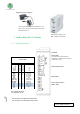
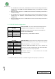
8.2 RS- 485 Switch configuration
RS-485 TOP ZONE: In order to enable the RS-485 protocol the
TOP ZONE must be configured as it is shown in the table.
Although the switch name only is referenced to RS-485 it is
also the same for the RS-232.
Having this set up, the R7 & R8 are disabled.
RS-485 LEFT ZONE: The H/F can be set up as ON or OFF. If it is wished
to use the RS-485 Half Duplex (A+, B-) it has to be ON. For using the
RS-485 Full Duplex (A+, B-, Y+, Z-) it has to be OFF.
The switch RE-RS485 and DE-RS485 must be set in ON mode. As
these pins are set to ON, the other 2 (I0.4, I0.5) must be set to OFF.
Being in OFF mode they are completely disabled.
The switches marked as “ – “ don’t interfere with the RS-485
communication protocol.
* To enable the RS-485 communication it is needed to configure also the jumpers, see Section 10
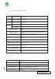
TOP ZONE
SWITCH
MODE
DI - RS-485
ON
R8
OFF
D0 - RS-485
ON
R7
OFF
LEFT ZONE
SWITCH
MODE
NC
-
H/F
ON/OFF
SCL/R5
-
SDA/I0.0
-
RE-RS485
ON
I0.4
OFF
DE-RS485
ON
I0.5
OFF