
Data Sheet

Page
19
Cat. Nº: ABOX-104-001-71
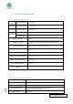
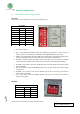
8 Switch configuration
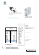
8.1 General Switches Configurations
LEFT ZONE.
Communications and inputs/outputs can not work simultaneously.
1. NC – Not Connected
2. H/F – Choosing between Half/Full Duplex for the RS485 communication. In order to use Full
Duplex, it has to be considered the TOP ZONE and the JUMPER ZONE(*see section 10).
3. SCL/R5 – Choosing between SCL (I2C) and R5. If the switch is ON, the R5 will be enabled and the
SCL will be disabled. If the switch is OFF, SCL will be now enabled and R5 disabled.
4. SDA/I0.0 - Choosing between SDA (I2C) and I0.0. If the switch is ON, the I0.0 will be enabled
and the SDA will be disabled. If the switch is OFF, SDA will be now enabled and R5 disabled.
1. RE-RS485 – If this switch is ON, the I0.4 switch must be set to OFF. Being in ON mode it enables
RE for the RS-485.
2. I0.4 – If this switch is ON, the RE-RS485 switch must be set to OFF. Being in ON mode it enables
the input I0.4.
3. DE-RS485 – If this switch is ON, the I0.5 switch must be set to OFF. Being in ON mode it
enables DE for the RS-485.
4. I0.5 – If this switch is ON, the DE-RS485 switch must be set to OFF. Being in ON mode it
enables the input I0.5.
TOP ZONE.
Communications and outputs can not work simultaneously.
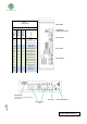
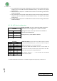
LEFT ZONE
SWITCH
ON
OFF
NC
-
-
H/F
Half Duplex
Full Duplex
SCL/R5
R5
SCL
SDA/I0.0
I0.0
SDA
RE-RS485
RE-RS485
I0.4
I0.4
I0.4
RE-RS485
DE-RS485
DE-RS485
I0.5
I0.5
I0.5
DE-RS485
TOP ZONE
SWITCH
ON
OFF
D1 - RS-485
RS-232/485
R8
R8
R8
RS-232/485
D0 - RS-485
RS-232/485
R7
R7
R7
RS-232/485