
Data Sheet

Page
18
Cat. Nº: ABOX-104-001-71
Base
(common unit)
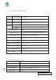
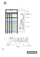
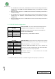
RIGHT ZONE
Ardbox
Connector
Arduino Pin
RS-485 HD*
Arduino Pin
RS-485 FD*
Function
B-
A+
Z-/A0.1
Y+/A0.0
R4
R5
I0.9
I0.8
I0.7
I0.6
I0.5
1
I0.4
1
I0.3
2
I0.2
2
I0.1
I0.0
1
R6
R7
1
R8
1
-
-
11
13
5
3
A5
A4
A3
A2
A1
A0
8
4
12
2
7
0
1
-
-
-
-
5
3
A5
A4
A3
A2
A1
A0
8
4
12
2
7
0
1
RS485
RS485
RS485/Analog Output
RS485/Analog Output
Relay 4 Out
Relay 5 Out
Analog/Digital Input
Analog/Digital Input
Analog/Digital Input
Analog/Digital Input
Analog/Digital Input
Analog/Digital Input
Digital Input/ Interrupt
Digital Input/ Interrupt
Digital Input/ Interrupt
Digital Input/ Interrupt
Relay 6 Out
Relay 7 Out
Relay 8 Out
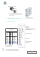
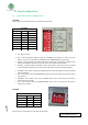
Power LED Arduino Reset button
Input / Output
LED
RIGHT ZONE
RS-485 pinout
Analog Outputs Pinout
Relay Outputs
Inputs pinout
Relay Outputs
Config switch *
(see section 9 for communications
configuration)