
Data Sheet

Page
17
Cat. Nº: ABOX-104-001-71
- Suggested power suppliers
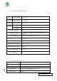
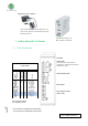
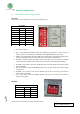
7 Ardbox Relay HF I/O Pinout:
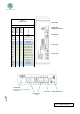
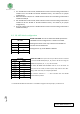
7.1 Zone Connections
HS*: Hardware Serial
SS*: Software Serial
1
See section 9 to enable these connections
2
See section 10 to enable these connections
Base
(common unit)
LEFT ZONE
Ardbox
Connector
Arduino Pin
RS-232 HS*
Arduino Pin
RS-232 SS*
Function
MISO
MOSI
SCK
RESET
5VdC
GND
RX-RS-232
1,2
TX-RS-232
1,2
SDA-PIN2
1
SCL-PIN3
1
R1
R2
R3
GND
24V
14
16
15
-
-
-
1
0
2
3
10
9
6
-
-
14
16
15
-
-
-
4
8
2
3
10
9
6
-
-
SPI-MISO
SPI-MOSI
SPI-CLOCK
SPI-RESET
5V Output
GND
Serial/RS232
Serial/RS232
I2C/SPI SS
I2C/SPI SS
Relay 1 Out
Relay 2 Out
Relay 3 Out
GND
-
* Not recommended for industrial applications. The
Jack connector needs to be removed and use the live
and GND connectors.
LEFT ZONE
Switch config*
(see section 9 for Communications
configuration. Enabling Communications
disables some I/Os)
Communications pinout
Relay Outputs
Power supply connectors
(24Vdc – Gnd)
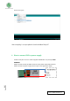
Din RAIL Power Supply, ac-dc,
30W, 1 Output 1.3A at 24Vdc