USER GUIDE PLC Arduino ARDBOX 20 I/Os Relay HF Cat.
Page Cat.
PLC Arduino ARDBOX 20 I/Os Relay HF User Guide Revised March 2018 Page 3 This user guide is for version PLC Arduino ARDBOX 20 I/Os Relay HF, with Reference name Ref.IS.AB20REL-HF only. For older versions refer to user guide with Cat. No. ABOX-004-001-70 Cat.
Preface This User Guide is been implemented by Boot & Work, S.L. working under the name Industrial Shields. Purpose of the manual The information contained in this manual can be used as a reference to operating, to functions, and to the technical data of the signal modules, power supply modules and interface modules. Intended Audience This User Guide is intended for the following audience: Persons in charge of introducing automation devices. Persons who design automation systems.
Application Considerations and Warranty Read and Understand this Manual Please read and understand this manual before using the product. Please consult your comments or questions to Industrial Shields before using the product. Application Consideration THE PRODUCTS CONTAINED IN THIS DOCUMENT ARE NOT SAFETY RATED. THEY SHOULD NOT BE RELIED UPON AS A SAFETY COMPONENT OR PROTECTIVE DEVICE FOR ENSURING SAFETY OF PERSONS, AS THEY ARE NOT RATED OR DESSIGNED FOR SUCH PURPOSES.
Disclaimers Weights and Dimensions Dimensions and weights are nominal and they are not used for manufacturing purposes, even when tolerances are shown. Performance Data Performance data given in this manual is provided as a guide for the user in determining suitability and does not constitute a warranty. It may represent the result of INDUSTRIAL SHIELDS’s test conditions, and the users most correlate it to actual application requirements.
Warranty and Limitations of Liability Warranty Industrial Shields’s exclusive warranty is that the products are free from defects in materials and workmanship for a period of one year (or other period if specified) from date of sale by Industrial Shields. INDUSTRIAL SHIELDS MAKES NO REPRESENTATION OR WARRANTY, EXPRESS OR IMPLIED, REGARDING MERCHANABILITY, NON-INFRINGEMENT, OR FITNESS FOR PARTICULAR PURPOSE OF THE PRODUCTS.
Table of Contents 1 ARDBOX ....................................................................................................................... 9 2 Precautions................................................................................................................ 10 3.1. Arduino Board ................................................................................................... 10 3.2. Intended Audience ...................................................................................
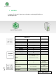
1 ARDBOX A compact PLC based in Open Source Hardware technology. With different Input/Outputs Units. COMPACT PLC ARDUINO ARDBOX 20 I/Os RELAY HF Alimentation Voltage Fuse protection (2.5A) Polarity protection 12 to 24Vdc Max. current consumption 1,5A Size 100x45x115 Clock Speed 16MHz 32KB of which 4KB are used by bootloader 2.5KB Flash Memory SRAM EEPROM Communications TOTAL Input points TOTAL Output points 1KB I2C – USB -- RS232 -- RS485 – SPI 10 10 Digital range:5 to 24 Vdc (3.8 to 25.
I min: 5/10 mA Separated PCB ground Digital Isolated range: 5 to 24 Vdc (4.6 to 25.4 Vdc) OUTPUTS Analog range: 0 to 10 Vdc Imax: 5A Relay 8 Analog 8 bits 2 Expandability I2C*– RS232* - RS485* – SPI – USB Reference (See Relay Specification in i/o technical details) 0 to 10 Vdc I max: 40 mA Separated PCB ground IS.AB20REL.HF * By using this type of signal you can no longer use Digital signal You must read product Datasheet. 2 Precautions 3.1.
3 Technical Specifications 3.1 General Specifications: Power supply voltage DC power supply 12 to 24Vdc Operating voltage range DC power supply 11.4 to 25.4Vdc Power consumption DC power supply 30VAC max. Power supply voltage 12 to 24Vdc Power supply output capacity 1.3A External power supply Insulation resistance 20MΩ min.at 500Vdc between the AC terminals and the protective earth terminal. Dielectric strength 2.300 VAC at 50 to 60 HZ for one minute with a leakage current of 10mA max.
Flash Memory Program capacity (SRAM) EEPROM Clock Speed 32kb of which 4 kb are used by bootloader 2.5kb 1kb 16MHz 4 Software interface Industrial Shields PLC are programmed using Arduino IDE, which is a software based on the C language. They can also be programmed using directly C but it is much easier working with Arduino IDE as it provides lots of libraries that helps in the programming. Furthermore Industrial Shields provides boards for programming the PLCs much easier.
3. Press OK to save the changes. 4. Go to: Tools -> Board: … -> Boards Manager 5. Search for industrialshields on the searcher. Page 13 6. Click install (selecting the latest version). Following this steps you will be able to use now the Industrial Shields Boards: Cat.
Once it is selected the Ardbox Family or M-Duino family an extra option will appear on Tools: There, it can be selected the exact model for every family. Also there are some examples of programming in File -> Examples -> Ardbox Family. https://github.com/IndustrialShields/ Page 14 Furthermore there are some extra libreries that can be found in Industrial Shields github. Cat.
5 How to connect PLC Arduino to PC - Connect USB port from PLC to PC. NOTE: Ardbox Family use micro USB cable. - Open Arduino IDE interface: - Select Industrial Shields boards -> Ardbox Family - Select the correct Ardbox Relay Board.
- Select correct port. Now everything is set up to upload a sketch to Ardbox Relay HF 6 How to connect PLC to power supply - Page 16 - Ardbox Family PLCs are 12 to 24Vdc supplied. IMPORTANT: The polarity IS NOT REVERSAL! Make sure that the live and GND connector of the power supply match the PLC. Make sure that the power supply mains output is not higher than 24Vdc. Cat.
- Suggested power suppliers * Not recommended for industrial applications. The Jack connector needs to be removed and use the live and GND connectors. 7 Ardbox Relay HF I/O Pinout: 7.1 Din RAIL Power Supply, ac-dc, 30W, 1 Output 1.3A at 24Vdc Zone Connections LEFT ZONE Switch config* (see section 9 for Communications configuration.
Base (common unit) RIGHT ZONE RS-485 pinout Analog Outputs Pinout Function Arduino Pin RS-485 FD* Arduino Pin RS-485 HD* Ardbox Connector RIGHT ZONE B- - - RS485 A+ - - RS485 Relay Outputs Z-/A0.1 11 - RS485/Analog Output Y+/A0.0 13 - RS485/Analog Output R4 5 5 Relay 4 Out R5 3 3 Relay 5 Out I0.9 A5 A5 Analog/Digital Input I0.8 A4 A4 Analog/Digital Input I0.7 A3 A3 Analog/Digital Input I0.6 A2 A2 Analog/Digital Input I0.
8 Switch configuration 8.1 General Switches Configurations LEFT ZONE. Communications and inputs/outputs can not work simultaneously. LEFT ZONE SWITCH ON OFF NC - - H/F Half Duplex Full Duplex SCL/R5 R5 SCL SDA/I0.0 I0.0 SDA RE-RS485 RE-RS485 I0.4 I0.4 I0.4 RE-RS485 DE-RS485 DE-RS485 I0.5 I0.5 I0.5 DE-RS485 1. NC – Not Connected 2. H/F – Choosing between Half/Full Duplex for the RS485 communication.
1. D1 – RS-485: If this switch is ON, the R8 switch must be set to OFF. Being in ON mode it enables DI for the RS-485 and RS-232 Hardware Serial ( see section 9 for jumper configuration) 2. R8: If this switch is ON, the DI – RS-485 switch must be set to OFF. Being in ON mode it enables the Relay 8. 3. D0 – RS-485: If this switch is ON, the R7 switch must be set to OFF. Being in ON mode it enables D0 for the RS-485 or RS-232 Hardware Serial ( see section 9 for jumper configuration) 4.
RS- 232 Switch configuration 8.3 TOP ZONE SWITCH MODE DI - RS-485 ON R8 OFF DO - RS-485 ON R7 OFF RS-232 TOP ZONE: In order to enable the RS-232 protocol the TOP ZONE must be configured as it is shown in the table. Although the switch name only is referenced to RS-485 it is also the same for the RS-232. Having this set up, the R7 & R8 are disabled. RS-232 LEFT ZONE: As both RS-232 & RS-485 can’t work at the same LEFT ZONE SWITCH MODE NC - H/F - SCL/R5 - SDA/I0.0 - RE-RS485 OFF I0.
9 Jumper configuration 9.1 General jumper configuration JUMPER ZONE 1 LEFT RIGHT Y+ Z- ENABLE ENABLE A0.0 A0.1 JUMPER ZONE 2 LEFT RIGHT I0.2 I0.3 D4 D8 RS-232 RS-232 JUMPER ZONE 3 UP RS-485 D1 RS-232 DOWN RS-485 D0 RS-232 This jumper zone makes the selection between using the RS-485 Full Duplex or the Analog Outputs. If it is wanted to use the RS-485 Full Duplex communication protocol the Y+ must be connected to ENABLE, and Z- also connected to ENABLE.
10 Hardware Serial RS-232 & RS-485 Configuration 10.1 Hardware Serial RS-232 In order to enable the Hardware Serial RS-232 the total configuration of the Ardbox Relay HF will be: Switch configuration: LEFT ZONE TOP ZONE SWITCH MODE DI - RS-485 ON R8 OFF DO - RS-485 ON R7 OFF SWITCH MODE NC - H/F - SCL/R5 - SDA/I0.0 - RE-RS485 OFF I0.4 ON DE-RS485 OFF I0.5 ON Jumper configuration: JUMPER ZONE 1 JUMPER ZONE 3 JUMPER ZONE 2 LEFT RIGHT LEFT RIGHT NC NC I0.2 I0.
10.2 Hardware Serial RS-485 In order to enable the Hardware Serial RS-485 the total configuration of the Ardbox Relay HF will be: Switch configuration: LEFT ZONE TOP ZONE SWITCH MODE DI - RS-485 ON R8 OFF DO - RS-485 ON R7 OFF SWITCH MODE NC - H/F ON/OFF SCL/R5 - SDA/I0.0 - RE-RS485 ON I0.4 OFF DE-RS485 ON I0.5 OFF Jumper configuration: JUMPER ZONE 1 HALF DUPLEX LEFT RIGHT LEFT RIGHT Y+ Z- I0.2 I0.3 ENABLE ENABLE D4 D8 A0.0 A0.
11 I/0 technical details Page 25 Relay Cat.
Page 26 Analog Out Turn-on Cat.
Analog Out Turn-off Analog/Digital Input Turn-on Page 27 Analog/Digital Input Turn-off Cat.
12 Connector details The connector inside the PLCs that mounts on the PCB is MC 0,5/10-G-2,5 THT – 1963502 from Phoenix contact. MC0,5/10-G-2,5THT For I/O and power supply there is a FK-MC 0,5/10-ST-2,5 - 1881406 connector from Phoenix contact. FK-MC 0,5/10-ST-2,5 Article reference MC 0,5/10-G-2,5 THT Height 8,1mm Pitch 2,5mm Dimension 22,5mm Pin dimensions 0,8x0,8mm Pin spacing 2,50mm Article reference FK-MC 0,5/10-ST-2,5 Rigid conduit section min. 0,14 mm² Rigid conduit section max.
13 ARDBOX Family Dimensions: 14 DIN rail mounting: Page 29 45mm width Cat.
About Industrial Shields: Direction: Fàbrica del Pont, 1-11 Zip/Postal Code: 08272 City: Sant Fruitós de Bages (Barcelona) Country: Spain Mail: industrialshields@industrialshields.com Page 30 Telephone: (+34) 938 760 191 / (+34) 635 693 611 Cat.