Scale Basic Reference and Tutorial Version 4.
Scale Basic 4.2E Table of Contents Table of Contents Introduction .........................................................................................................1 EZ Link .................................................................................................................2 EZ Link Installation .................................................................................................................... 2 EZ Link Configuration ....................................................
Scale Basic 4.2E Introduction Introduction Scale Basic in a programming language that is used to modify the functions of a weight indicator. This makes it possible for the weight indicator to be customized to fit a wide variety of weighing applications The first section of this manual describes how to use EZ Link, a computer program that runs on a PC computer under Microsoft’s ‘Windows’ operating system. EZ Link connects the indicator to a PC computer.
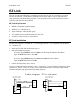
Scale Basic 4.2E Tutorial EZ Link EZ Link is a Microsoft Windows compatible program that you can use to configure, program, and test the indicator. The Windows graphical user interface makes it easy to enter and view setup parameters and Scale Basic programs. The setup data can be saved to disk and it can be written to and read from the indicator. EZ Link Requirements • • • • • IBM PC compatible computer/laptop Windows 3.1 or Windows 95 Approximately 1.
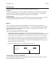
Scale Basic 4.2E Tutorial EZ Link Configuration The indicator’s communications port 2 [Com Port 2] defaults to 9600 baud, 8 bits, no parity. The EZ Link program defaults to the same values. If the defaults have not been changed, then configuration is not required. Check the indicator’s Com Port 2 parameters.
Scale Basic 4.2E Tutorial EZ Link Test Use this procedure to test the connection between the indicator and the PC. On the PC: If you are using Windows 95, access the Hyperterm program from the Start menu / Programs / Accessories / Hyper Terminal. In Windows 3.1 use the Terminal program. Configure the Hyperterm program using the parameters entered above for the indicator. On the indicator: Hold the CLEAR key down and press the ENTER key to enter the configure mode. Enter CFG 69.
Scale Basic 4.2E Tutorial Test 5 Press the indicator’s CLEAR key to exit diagnostic test 4. Enter test number 6 and then press the ENTER key. This test transmits data out of the indicator’s serial communications port 2. The display prompts: “OUT 0”. Press the indicator’s ENTER key to send data. Serial Port 2 transmits “1234567890ABCDEF” and prompts “OUT 1” to indicate that 1 transmission has occurred. The transmitted data should appear on the PC terminal screen.
Scale Basic 4.2E Tutorial Event Driven Programming This section provides an introduction to event driven, computer program design. Program Design The first step in computer programming is to create a ‘program design’. The first mistake that a programmer can make is to give insufficient attention to designing a program. Give extra attention to this phase of programming; you will be well rewarded for your effort.
Scale Basic 4.2E Tutorial Sequence of operation Enter target weight data: Use the indicator’s built in memory register input function. The operator sets memory registers 1, 2, and 3 for container 1, 2, and 3. Select a target weight. Use the F1 key to initiate target weight selection. The display prompts “Con”. The operator enters the container number that will be filled. Monitor weight for over/under: use Power On Start to initiate underweight scan by activating user function1.
Scale Basic 4.2E Tutorial Event Driven Programming Event Driven programming is useful for ‘real time’ applications. Real time applications are those which depend on real events that happen when they happen. For example, a start switch closure, setpoint trip level, process monitoring, are real events that the computer monitors but the timing of the events are not controlled by the computer. The most widely available programming model is the ‘sequential programming’ method.
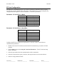
Scale Basic 4.2E Tutorial Design Template To help in the design process, we will use the following design template. The first 4 sections (Application Description, Outputs, Inputs, Sequence of operation are used in program design. The remaining sections are used in program implementation. [Application Title] Application Description. This is a general description as given by the customer. Outputs list the outputs that will be produced by this application.
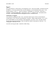
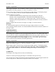
Scale Basic 4.2E Tutorial Scale Basic Tutorial The following section assumes that the indicator is connected to a PC computer using EZ Link. If you are not connected, then use the keyboard entry techniques described in the user’s manual. Some of the examples used in the tutorial use the TTL Outputs (Relay outputs). Use the following circuit to view the results of the Relay out commands.
Scale Basic 4.2E Tutorial Use the template above to enter and test the program. The program can be extracted from the Event and Function sections of the template. (If you are using keyboard entry, enter the data listed in parenthesis () ). 1. Invoke the EZ Link program. 2. From the Event section: Set Keyboard Events / F1 key = User1 3. From the Function section: Scale Basic / User 1 enter the following program: (parameter 72, Fn.
Scale Basic 4.2E Tutorial The permanent storage registers (Fixed43…50) are used for permanent storage of numbers. These registers are stored in EA-ROM memory, they retain their value if power is lost. They are set by using the configure function for parameters 43…50 (EZ Link Fixed Registers). It is NOT good practice to change these registers using Scale Basic; the changes will be lost on power up or when the configure function is invoked.
Scale Basic 4.2E Tutorial The above function uses Memory1, 2, and 3. The memory registers used are listed in the Parameters section of the design template. This section of the template is used to manage resources such as memory registers, and to list parameters that need to be configured such as Fixed registers or print labels. Parameter Used for Memory1 Memory2 Memory3 operator input 1 operator input 2 sum Use the template above to enter the program (configure F1 key and User1 function).
Scale Basic 4.2E Tutorial Setpoint Monitors Purpose1: to monitor 2 registers and activate a scale basic function when the lower register is greater than or equal to the upper register ( trigger when: lower register >= upper register ). Purpose2: to monitor a condition code and activate a scale basic function when the condition is true or false. Set the upper register to True or False then the lower register to a condition code.
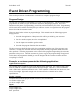
Scale Basic 4.2E Tutorial The Setpoint Monitor is used to generate the next event. When the setpoint event occurs, it activates user function 2 which turns off the fill valve. Event Function Comments F1 key Setpoint 1 User 1 User 2, Start Fill operation trigger when Net >= Fixed43 (setpoint amount) Configure the Setpoint 1 event with the Upper register = Fixed43 and the Lower register = Net weight register.
Scale Basic 4.2E Tutorial 6. In EZ Link select File, Save As, then type in “test3” then click OK. This saves the program onto disk. 7. In EZ Link select the UP (Upload) button. Click on file “test3.sf” then click on OK. 8. Press the F1 key on the indicator. Press the Gross/Net key to verify that the tare weight has been read. The LED indicator should be on (Relay out 1). Add 1000 lb. to the scale using the scale simulator. The LED light should turn off.
Scale Basic 4.2E Tutorial Scale Basic function is executed. There are 5 timer records that contain the following data: Time interval time interval in tenths of a second (x0.1sec). Max = 6553.0 seconds. Scale Basic Function the scale basic function to execute when time-out occurs. Timers 1-4 must be reactivated with a Timer on instruction to begin again. Timer 5 is an auto-reload timer.
Scale Basic 4.2E 3. Tutorial Scale Basic enter the following program: Function Instructions Comments User 1 Timer on, 5 End User 2 If, Flag1 Flag off, 1 Relay off, 1 Else Flag on, 1 Relay on, 1 End if End turn on timer 5. end of function if LED flag turn off LED flag turn off LED Else turn on LED flag turn on LED End if End of function 4. Upload the program to the indicator. Press the F1 key. The LED flashes at 0.2 second intervals.
Scale Basic 4.2E Reference Reference The reference is divided into 3 sections: 1. Instruction Reference: details each Scale Basic instruction and provides examples. 2. Condition Codes: details the condition codes and how they are used. 3. Built in Functions: the built in functions that can be used with Gosub and Goto instructions. Instruction Reference Add [r] = [a] + [b] 200 [r] [a] [b] Purpose: add registers [a] & [b], put the result into register [r].
Scale Basic 4.2E Test for Net >= Fixed43 Compare, Net, Fixed43 If not, Negative Relay off, 1 End if Copy [To] [From] Reference If Net >= Setpoint Fixed43 turn off relay 1 End if 206 [to] [from] Purpose: copy the contents of register [from] to register [to] Remarks: copy does not affect the condition codes.
Scale Basic 4.2E Reference Remarks: sets condition codes Positive, Negative, and Zero to reflect results. The decimal position of the result before the divide determines the decimal position of the result after the divide. Divide by 0 sets the result to 0. NOTE: it is preferable to do a multiply instead of a divide (see Mul example). Example: convert net weight pounds to tons. Register Fixed43 is set to 2000. Dp adjust, Memory1, 2 Set memory1 decimal position = 0.
Scale Basic 4.2E Reference Remarks: Use this instruction to alert the operator that an error condition has occurred. The message is displayed until the operator presses any key. Example: register Fixed43 is set to the maximum weight allowed in a weigh hopper. Compare, Gross, Fixed43 If, Positive If Gross weight > Maximum All off turn off all setpoint monitors, relays, and timers Error msg, 9 display “Err 9” End Exit function End if End if over-weight error Flag on / Flag off (flag no.
Scale Basic 4.2E Reference The prompt is displayed for 0.7 seconds, then if the register is non-zero, the register data is displayed. If the register data is zero, then the prompt is displayed until the operator enters data. Condition codes Positive, Negative, and Zero are set to reflect data input. Press the Clear key to abort data entry and leave the register unchanged.. NOTE: use the Dp adjust instruction for data entry with decimal points. Example: get the percent of moisture.
Scale Basic 4.2E Get id, Memory1 If, Zero Error msg, 8 End if End Reference Open Id 25 If the Id was not found display error message 8 End if End of function Gosub (function no.) 243 [nnn] Purpose: to execute a function (subroutine) from within a function and return to the calling function at the instruction after the Gosub instruction. Remarks: a subroutine can be called from within a subroutine (this is called nesting). The maximum level of nesting is 8; i.e.
Scale Basic 4.2E Flag on, 1 Display Memory1 End if End Reference turn on flag 1 set to display Memory1 (total) End if End of function If not (condition) / Else / End if 242 [nnn] / 251 / 240 Purpose: to control program flow using a condition code. Remarks: sometimes it is more meaningful or more convenient to test for a false condition rather than a true condition. In these situations, use the If not instruction.
Scale Basic 4.2E Reference Set Memory1, 3 Index id, Memory1 Set Id1, 0 Write id End Memory1 = 3 Open ID record 3 (the 3d record in memory) Set ID record 3, Id register1 to 0 Write the most recently accessed ID to memory. End of function Keybd off / Keybd on 227 / 226 Purpose: to prohibit access to the keyboard when running a critical function. The Clear key will turn the keyboard on if it has been turned off.
Scale Basic 4.2E Set Memory1, 20 Loop1 Index id, Memory1 Set Id1, 0 Dec Memory1 If Positive Next1 End if End Make id [r] Reference For Memory1 = 20 down-to 0 ID[Memroy1].register 1 = 0 End For … End of function 235 [r] Purpose: to open an ID record. If the ID number in register [r] in not found, open a new ID record and assign ID[r] to it. Remarks: condition code Positive is set true if the Id is made or found, condition code Zero is set true if the Id could not be made (memory full).
Scale Basic 4.2E Reference Next1 (see Loop1 / Loop2 instruction) 246 Next2 (see Loop1 / Loop2 instruction) 248 Nop 254 Purpose: no-operation, this instruction does nothing. Remarks: rarely used in scale basic. Example: Nop No-operation, do nothing Prompt (nnn) (nnn) (nnn)… 232 [nnn] [nnn]…[0] Purpose: display a message on the numeric display. Remarks: this instruction is used to display status or to prompt the user for data input.
Scale Basic 4.2E Reference Relay on, 10 turn relay number contained in Memory10 on Example: turn off all relays. If scale is at center of zero, turn on relay 3. Relay off, 0 turn off all relays If, Centerz If scale is at center of zero Relay on, 3 turn on relay 3 End if End if End End of function Resume (see Suspend instruction) 250 Set [r] (nnn) 209 [r] [nnn] Purpose: set a register to a value between 0 and 255. Remarks: values greater than 255 are replaced by the modulo of 255.
Scale Basic 4.2E Sign Reference [r] 207 [r] Purpose: to set condition codes based on the value in register [r]. Positive is set if the register is greater than 0, Negative is set if the register is less than 0, Zero is set if the register is zero. Remarks: Example: Check for scale below zero.
Scale Basic 4.2E Reference Timer off / Timer on (n) 225 [n] / 224 [n] Purpose: to activate / de-activate a timer. Remarks: the active timers are scanned by the event monitor. When an active timer counts down to 0 (times out) it activates a scale basic function and de-activates itself. Timer off 0 turns off all timers. NOTE: timer 5 is a special timer. It is an ‘auto-reload’ timer. When it times out, it automatically restarts itself, and then executes a scale basic function.
Scale Basic 4.2E Reference Fn. 4: All off End Txcom1 / Txcom2 turn off all timers, relays, etc. End of function. (n) 237 [nnn] / 238 [nnn] Purpose: to transmit a message from serial communications port 1 / port 2. Remarks: the Txcom instructions transmit formatted page output with n = 1, 2, 3, or 4 (for pages 1, 2, 3 & 4). The Txcom instructions transmit labels if n = 32, 33, 34, 84, 85, 86, 87 where 32, … = print labels. The print labels can be fixed messages or can be embedded with register data.
Scale Basic 4.2E Reference Remarks: this instruction takes a minimum of 3 A/D conversion cycles. Press the Clear key to abort Valid wt command; also aborts the scale basic function using this instruction, and all calling functions (unwinds subroutine stack). Example: Write id Valid wt Gosub Print1 wait for valid weight. Abort all if Clear key pressed. print format 1 228 Purpose: write ID data back to ID memory.
Scale Basic 4.2E Reference Condition Codes The condition codes are used in the IF instruction to determine if the instructions following the IF are to be executed. The arithmetic condition codes are set every time a calculation instruction is performed. The Setpoint monitor condition codes are true if the monitor corresponding to the condition code is active. The following table lists the condition codes. Altunits 109 Purpose: true if display is in alt-units mode.
Scale Basic 4.2E Reference Flags 10 -16 Purpose: Enables control of status LEDs on display panel (Gross, Net, Motion. Zero, Lb, Kg) Remarks: Flag 10 is used to allow turning on and off the status LED displays, flags 11-16. Example: Use the F1 & F2 keys to toggle on and off the all the displays. Individual LEDs could be used to show an over under or between status, high or low status as a bar graph or to emulate a masters display in a master/ slave network. Set CFG 57 to 1.
Scale Basic 4.2E Netmode Reference 103 Purpose: true if display is in Net mode. Overload 115 Purpose: true if scale status = Overload Positive 101 Purpose: true if previous calculation result was Positive. Remarks: Also set by Get id and Make id to signal that the instruction was successful. Printable 108 Purpose: true if the weight registers (Gross/Net) contain printable (handbook 44) weight.
Scale Basic 4.2E Reference Built in Functions Close id 142 Purpose: use after Open id or Open new to save ID data to memory. Remarks: the Close id function and Write id instruction perform identical functions. ID data is read into the ID registers by the Make id, Get id, and Index id instructions or by the Open id, Open new, Read first, and Read next functions. If any ID data is modified, it must be written back to ID memory to make the change permanent.
Scale Basic 4.2E Reference Print1, Print2, Print3, Print4 133, 134, 135, 146 Purpose: to send formatted data to the printer. Remarks: there are 4 pages of print formats that can be configured. Page 1 defaults to print the Gross weight when the display is in Gross mode, Page 2 defaults to print Gross, Tare, and Net weights when the display is in the Net mode. Print1 prints page1, Print2 prints page 2, etc. Print mode 136 Purpose: to send formatted print pages to the printer.
Scale Basic 4.2E Reference Remarks: the Suspend instruction stops a Scale Basic function from executing, thus allowing the Event Monitor to scan for events. The Resume function reactivates the function that suspended, at the instruction following the Suspend instruction. Example: Timer1 is set for 4 second delay, then it activates the Resume function.
Scale Basic 4.2E Loop1 If Motion Update Next1 End if Gosub Print1 Update alt Reference While Motion on scale Update scale readings End While Motion Print page 1 145 Purpose: update alternate weight units registers. Remarks: the indicator is designed provide weights in 2 units of measure: primary and alternate units. The all weight calculations are performed in the primary weight units. The alternate unit weights are only calculated as needed.
Scale Basic 4.2E Reference Example Purpose1: trigger user function 1 when gross weight is greater than Memory register 12 (weight above setpoint). Upper register Memory12 Lower register Gross Execute Function User1 trigger user function 2 when Memory register 12 is greater than Gross weight (weight below setpoint).
Scale Basic 4.2E Reference Timer Events Purpose 1: to trigger a scale basic function after a set time interval. Purpose 2: to wait an interval of time inside a scale basic function. Remarks: Timers are activated using the Scale Basic instruction: Timer on [t]. When a timer is activated, the time interval is set into the timers countdown register. The countdown register decrements by 1 every 0.1 seconds. When the countdown reaches 0 the Scale Basic function is executed.
Scale Basic 4.2E Reference Flag on, 1 turn on flag 1 Relay on, 1 turn on relay 1 End if End if This example will cause relay output 1 to continuously turn on and off in 0.2 second intervals. TTL Input Events Purpose: execute a scale basic function when a TTL input is activated (shorted to ground). Remarks: TTL inputs 1 through 4 execute scale basic functions 1 through 4. The TTL inputs trigger when the input signal goes from TTL high to TTL low.
Scale Basic 4.2E Reference Example2: a bar code reader is used to read the tare weight for the scale. Setpoint 1 is configured to trigger when a bar-code message is received. Function 1 reads the bar-code data into the Tare register. Setpoint1: Upper register = True, Lower register = Barcode, Function = User1. Fn. 1: Get data, Tare End read bar-code data into the tare register. End of function Serial Communications Port 2 Input Purpose: execute commands received by communications port 2.
Scale Basic 4.2E Reference Remarks: xxx can be any valid register number. The data is transmitted in the form: nnnnnnnnn where nnnnnnnnn is the contents of register xxx, in a 9 character field, zero blanked. Example: the net weight is 1945 lb. The indicator receives R66 then it transmits the contents of the Net weight register in the form 1945.
Scale Basic 4.2E Reference S/I Purpose: Status / Idle pairs are used to verify that a remote station is available to accept commands. Remarks: network systems are normally setup in a master/slave configuration. The master units sends ‘S’ command to the slave unit. The slave replies with an ‘I’ status if it is on line and available. The Master receives the ‘I’ as a command to execute user function 14. Example: scan all network addresses for available stations. 1.
Scale Basic 4.2E Reference Registers There are 5 types of registers: memory registers, fixed registers, scale registers, Id registers and special purpose registers. Memory Registers Use memory registers for calculated setpoints and for operator entry setpoints. There are 16 memory registers. To access the registers, enter the memory register number (1 to 16) and press the ENTER key. The display prompts "rEg xx" for 1 second and then displays the contents of the register.
Scale Basic 4.2E Reference 61 62 63 64 65 66 Alt units - Gross weight Alt units - Tare weight Alt units - Net weight Gross Weight Tare Weight Net Weight ID Registers Each ID record in memory has 6 registers. The register data for an ID is available when it is "opened" (instructions Get id, Make id, functions Open id and Open new). The register data is written to an ID record when it is "closed" (instruction Write id and function Close id).
Scale Basic 4.2E Reference Time / Date Logging Modification 118 Time Time Register The Time register has the following uses: Copy, , Time The copy instruction only works when copying from Time to a decimal register. The current time and date is read from the clock and then copied in BCD format to the decimal register. Display Time The current time is read from the clock and then copied to the display.
Scale Basic 4.2E Reference Error Codes Err 0 Power on acquire zero error. Occurs when parameter 20 is set to acquire zero on powerup. If the scale is out of zero range or in motion then Err 0 occurs. Remove weight or wait for stable scale, then press Clear key. Err 1 Keyboard error. Occurs when a key is pressed while power-on test is in progress. Err 2 Restart Trap. The microprocessor accessed a non-existent memory location. Usual cause is electrical noise from the A/C power supply.
Scale Basic 4.2E Appendix A: Design Template Appendix A: Design Template Application Description. This is a general description as given by the customer. Outputs list the outputs that will be produced by this application. Inputs list the inputs required by this application. Sequence of operation describe the sequence of operation of this application.