IDS 410/422 Weight Indicator Installation/Calibration/Operation Version 1C 07/01/2010 Telephone Sales 714-921-9212 Out of State (USA) 800-854-3311 Technical Support 714-921-1353 FAX 714-399-0286 E-mail sales@industrialdata.com Postal address 3822 E. La Palma Ave. Anaheim Ca.
IDS 410/422 User's Manual INTRODUCTION 4 Organization of Manual Warranty Information 4 5 GENERAL DESCRIPTION 6 The IDS 410/422 Display and Keyboard Diagram The IDS 410/422 Display The IDS 410/422 Keyboard 6 6 7 INSTALLATION AND SETUP 8 Unpacking the IDS 410/422 Installation Guide Setup Guide NTEP Labeling Instructions 8 8 10 12 USING THE IDS 410/422 Keyboard Layout Select Mode of Operation (Parameter73) Modes of Operation Normal Mode (Mode 0) Print Weight and Total (Mode 1) Auto Print Weight a
IDS 410/422 User's Manual Parameter 5. Motion Detection Band (6) Parameter 6. Enable Display Blanking During Motion (no blanking) Parameter 7. Zero tracking Delay (1) Parameter 8. Zero Tracking Band (12) Parameter 9. Push Button Zero Percent (100) Parameter 10. Primary Units Type (1[lb]) Parameter 11. Decimal Point Position (0[no decimal point]) Parameter 12. Count–By (1) Parameter 13. Alternate Units Type (2[kg]) Parameter 14. Alternate Decimal Point (1) Parameter 15. Alternate Count-By (5) Parameter 16.
IDS 410/422 User's Manual PARAMETER FUNCTIONS Function 59. Display Calibration Audit Number Function 60. Calibrate Scale (deadload first) Function 61. Calibrate Scale (span first) Function 62. Calibrate (deadload only) Function 63. Adjust Gain Calibration Function 64. Configure Passwords Function 65. Configure Print Formats Function 66. Configure Time and Date Function 67. Display Operation Parameters Function 68. Print Operation Parameters Function 69. Diagnostic Tests Function 70.
IDS 410/422 User's Manual INTRODUCTION Congratulations on your purchase and welcome to the IDS 410/422 User's Manual. This manual describes the installation and operation of the IDS 410/422 weight indicator. The IDS 410/422/422 is a microprocessor based weight indicator with rugged design and state-of-the-art technology.
IDS 410/422 User's Manual WARRANTY INFORMATION INDUSTRIAL DATA SYSTEMS, INC. LIMITED WARRANTY. Industrial Data Systems, Inc., warrants that the products furnished are free from defects in material and workmanship and perform to applicable, published Industrial Data Systems, Inc., specifications for one (1) year from the date of shipment. THIS WARRANTY IS IN LIEU OF ANY OTHER WARRANTY EXPRESSED OR IMPLIED. IN NO EVENT SHALL INDUSTRIAL DATA SYSTEMS, INC.
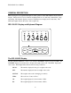
IDS 410/422 User's Manual GENERAL DESCRIPTION This section gives you a general description on the operation of the IDS 410/422's keyboard and display. The keyboard is used to initiate weighing functions, for data entry, maintenance, setup, and testing. The numeric display is used for weight and error display and for data entry. The LED status lights indicate the status of the weigh scale.
IDS 410/422 User's Manual The IDS 410/422 Keyboard The keyboard is used to initiate weighing functions and for setup of the IDS 410/422. Function Keys The function keys ZERO, TARE, GROSS/NET, UNITS and PRINT are used to Zero the scale, Tare the scale, switch the weight display between Gross and Net display, switch the weight display between LB and KG display, and Print the weight. The key function may be changed when the mode of operation is changed or configured by the user.
IDS 410/422 User's Manual INSTALLATION AND SETUP This section provides information about unpacking, installing, and setup of the IDS 410/422. It also directs the installer to the appropriate sections of the manual for hardware and setup installation. Unpacking the IDS 410/422 Installation begins with unpacking the IDS 410/422. Observe any instructions or cautions which appear in the shipping container. Check the items in the shipping container against the following item check list or the packing list.
IDS 410/422 User's Manual Connect IDS 410/422 to host device (optional) The Serial Communications Port 2 (TB3) provides a continuous output of scale data. This is used for connection to a host device such as a computer or to a remote display (scoreboard). Continuous output transmission can be enabled or disabled and the output format can be customized to interface with the host device (see OPERATIONS PARAMETERS - Continuous TX2 Format, page 5-10).
IDS 410/422 User's Manual Setup Guide Setup the IDS 410/422 in the following order: Initialize to Factory Defaults The IDS 410/422 is initialized at the factory. It must be re-initialized if the program memory (EPROM, U4 , RAM U5 ), the parameter memory (EAROM, U12) is replaced or if the optional clock chip in being installed for the first time. The Initialize function clears the memory and sets the configuration parameters to their default values. Use parameter function 70 initallize system.
IDS 410/422 User's Manual Calibrate the Weight Indicator Use Parameter Function (CFG 60 or 80) to calibrate the weight indicator (page 6-2). Parameter 80 is used for mutipoint linerization. Note: Parameter 79 must be set to a 1 to enable multipoint calibration before entering into parameter 80.
IDS 410/422 User's Manual NTEP LABELING INSTRUCTIONS Labeling Guidelines For NTEP Applications These guidelines pertain to the use of the IDS 410/422 in NTEP (National Type Evaluation Program) applications. If you are unfamiliar with NTEP, it is probable that this information can be disregarded for your application. NTEP has implications for “Legal-For-Trade” requirements only.
IDS 410/422 User's Manual Using the IDS 410/422 The IDS 410/422 weigh scale indicator has 8 modes of operation. See chapter 5 "Set Operation Parameters", configuration parameter 73 to select one of the modes. Keyboard Layout The IDS 410/422 has 5 function keys that are used for weighing functions, data entry, parameter setup, and testing. The setup functions are described in chapter 5 "Set Operation Parameters", the test functions are described in chapter 7 "Diagnostic Tests".
IDS 410/422 User's Manual Press the (+) or (-) key until the second from the right most digit is 7. Press the item key to advance to the next digit. Press the (+) or (-) key until the digit is 3 (display = 73). Press the enter key. Press the (+) or (-) keys to change the mode number. Press the ENTER key to store the displayed mode number. If you changed the mode number the display will prompt "rS Fnx" where 'x' is the new mode number. Press the enter key again.
IDS 410/422 User's Manual Gross/Net Press the Gross/Net key to alternate between Gross and Net display modes. UNITS Press the UNITS key to alternate between (lb) and (kg) display modes. PRINT Press the PRINT key to print weight data. Gross Weight (Page format 1) is printed if the IDS 410/422 is in Gross display mode, Gross/Tare/Net (page format 2) are printed in the Net display mode.
IDS 410/422 User's Manual Auto Print and Total Weighing/Multi-Container (Mode 2) The Multi-Container Weighing mode uses a Trip Weight to auto print and the PRINT key to print the accumulated total weight. This application is also used in applications where numbered weights are required with a total. Pallet filling, Truck loading ect; Place a container on the scale, when stable the weight is printed (Page 1). The following example shows the printout from 3 weights when the weight meter is in the GROSS mode.
IDS 410/422 User's Manual Unattended Auto Axle Weigh Short Scale (Mode 3) The Auto Axle Weigh and Print mode is used for unattended, short scale, vehical axle weighing applications.
IDS 410/422 User's Manual Unattended Auto Axle Weigh - Long Scale (Mode 4) The Automatic Axle Weigh mode is used for unattended, long scale, axle weighing applications. It operates the same as mode 5 except the weight on the scale is tared after each weighment.
IDS 410/422 User's Manual Peak Hold (Mode 5) The peak hold mode maintains the peak weight detected by the weight indicator. Display Peak Weight Use the GROSS/NET key to scroll thru the display options as follows: Initial mode: Display live gross weight. Gross LED on. First GROSS/NET press: Display live net weight. Net LED on. Next GROSS/NET press: Display gross peak weight. Gross LED flashing. Next GROSS/NET press: Display net peak weight. Net LED flashing.
IDS 410/422 User's Manual Fill to Setpoint/Bulkweigh (Mode 7) Clock Module required to back up setpoint Press the TARE key, the display prompts “SEt Pt” use the tare key and + - keys to enter in the setpoint value and press the Enter key (Print) to store it. Place an empty container on the scale. Press the UNITS key to begin filling. TTL output 1 turns on until the weight on the scale is equal or greater than the setpoint.
IDS 410/422 User's Manual SET OPERATION PARAMETERS This section describes the operation parameters of the IDS 410/422. Access Operation Parameters and Parameter Functions The parameters are accessed by holding the GROSS/NET key down and then pressing the UNITS key. The numeric display prompts "CFG xx", where xx is the currently selected parameter. Use the alternate key functions to select a parameter. Press the enter key to begin parameter data entry.
IDS 410/422 User's Manual Scale Parameters No.
IDS 410/422 User's Manual Display Intensity, Battery, Watch Dog Timer No Parameter Name Default 40 41 42 Display intensity Battery installed (CLOCK) Enable watch dog timer 10 0 (no) 1 (yes) Maximu m 15 1 1 Pass Maximu m 999999 999999 999999 999999 999999 999999 999999 999999 Pass Maximu m 255 255 255 255 255 255 Pass Field Setting 2 2 1 Fixed Setpoints No Parameter Name Default 43 44 45 46 47 48 49 50 Fixed setpoint 1 Fixed setpoint 2 Fixed setpoint 3 Fixed setpoint 4 Fixed setpoint 5 Fix
IDS 410/422 User's Manual Parameter Functions Fn. No 59 60 61 62 63 64 65 66 67 68 69 70 71 72 73 74 76 78 79 80 Function Name Password Level Display Calibration Audit Number Calibrate Scale - deadload first Calibrate Scale - span first Calibrate Deadload Only Adjust Gain Calibration Configure Passwords Configure Print Formats Set Time and Date Display Operation Parameters Print Operation Parameters Diagnostic Tests Initialize Operation Parameters to factory defaults.
IDS 410/422 User's Manual Parameter 1: Load Cell mv/V (3 mv/v) The IDS 410/422 can be used with load cell outputs of 1 mv/V, 2 mv/V, or 3 mv/V. Enter a 1, 2, or 3 for the load cell type used in your application. NOTE: there are 2 additional settings: 0 for high gain (0.5mv/v inputs) and 4 for low gain (6 mv/v inputs). Parameter 2: Digital Filter (9) The digital filter removes scale vibrations and other noise signals from the weight display. The filter range is between 0 and 18.
IDS 410/422 User's Manual Parameter 5: Motion Detection Band (6) The motion band is used by the MOTION DETECT function to determine if the scale is in motion (not stable). If the amount of change between display updates is greater than the motion band, a MOTION status is generated (unstable condition). The motion band is entered in units of 1/4 dd, i.e.. For a motion band of: 1/2 display division enter 1/2 x 4 = 2. 2 display divisions enter 2 x 4 = 8. 4.5 display divisions enter 4.5 x 4 = 18.
IDS 410/422 User's Manual Parameter 10: Primary Units Type (1 [lb]) The scale is calibrated in the primary units. The UNITS key is used to toggle the weight display between primary units and alternate units. Enter the number that corresponds with the primary units: 0 = UNDEFINED, units are not printed. 1 = lb 2 = kg 3 = ton 4 = tne 5 = gram 6 = oz 7 = use print label 1 for units. 8 = use print code 1 for units. NOTE: when parameter 10 is changed, parameters 13 and 16 must be programmed.
IDS 410/422 User's Manual Parameter 13: Alternate Units Type (2 [kg]) Alternate units are the alternate display and print unit of measure that can be used in addition to the primary units. The UNITS switch on the IDS 410/422's keyboard toggles the weight display between primary units and secondary units. 0 1 2 3 4 5 6 7 8 = UNDEFINED, units are not printed. = lb = kg = ton = tne = gram = oz = use print label 1 for units. = use print code 1 for units.
IDS 410/422 User's Manual Parameter 17: Full Scale Graduations (10,000) Enter the number of graduations at full scale. The full-scale graduations are calculated using the count-by, decimal position, and full-scale weight. Full Scale Graduations = Full Scale Weight / count-by . For example, if Full Scale Weight = 600.0 and count-by = 0.2 then Full Scale Graduations = 600.0 / 0.2 = 3000. Parameter 18: Overload Graduations (10,200) Enter the number of graduations at which the scale is in overload status.
IDS 410/422 User's Manual Serial I/O Ports The IDS 410/422 is equipped with two bi-directional serial communication ports that can communicate to an optional printer, a computer, bar code reader, a score board or other serial communication devices. The baud rate and format can be set independently for each port. Serial port 1 is normally used to output weight data and ID reports to a printer. Serial port 2 is normally used for continuous output of weight data.
IDS 410/422 User's Manual Parameter 25: Serial Port 2 Mode (4 [8 data bits, no parity] ) Enter the mode number from the table below to select the mode parameter in the mode description column.
IDS 410/422 User's Manual Parameter 28: TX2 Format (2 Condec data format) If parameter 27 is set to 0 (continuous tx), parameter 28 determines what is sent: 1-AND: ,, status: OL (overload), ST (stable), US (unstable, in motion) mode: GS (gross mode), NT (net mode) polarity: + (positive weight), - (negative weight) weight: 7 characters data, NOT zero blanked, with decimal point units: lb, kg, t (ton), tn (tonne), g (gram), oz terminate: lf, cr (line feed
IDS 410/422 User's Manual Printer Parameters The IDS 410/422 provides a universal printer interface for various printers. The printer interface allows you to select and customize the data output for serial printers. Parameter 30: Auto Print LF after CR (1 [yes]) Some printers require a line feed character (LF) to advance the paper and some printers advance the paper with only a carriage return character (CR). Enter a 1 to automatically add a line feed after a carriage return.
IDS 410/422 User's Manual Parameters 35, 36, 37, and 38: Print Codes The IDS 410/422 provides 4 programmable print codes. The print codes are used to send special setup parameters to the printer, such as select print size or select print font. Each print code is up to 4 characters long. Consult your printer manual for the print codes that you may want to use. Enter the codes in decimal format (an ASCII carriage return = 13). Select parameter 35 to begin print code 1 entry.
IDS 410/422 User's Manual Parameters 51-56: Keyboard Event Functions The keyboard event functions determine what actions take place when a key is pressed. The Power on start function activates a function when power is applied to the weight indicator. These parameters are set by the Mode of Operation selection (parameter 73) as needed.
IDS 410/422 User's Manual PARAMETER FUNCTIONS The parameter functions are used to set parameters that are too complex for a single numeric entry. The following table lists the parameter functions: Parameter Functions Fn. No.
IDS 410/422 User's Manual Function 59: Display Calibration Audit Number Use function 59 to view the calibration audit number , the configuration number, the software ID number, and the status of the internal function lock. The IDS 410/422 provides a calibration audit number and a configuration number. They are used to indicate changes to calibration data and configuration data and can be used in place of mechanical seals by some regulatory agencies.
IDS 410/422 User's Manual Function 61: Calibrate Scale - Span First Use function 61 to calibrate the scale by reading the span first and then reading the deadload. (This function does not change the internal A/D deadload factor). Set the Scale Operation Parameters before using function 61. Best results are obtained when the IDS 410/422 and load cells have reached thermal equilibrium (power applied for approximately 30 to 120 minutes depending on load cell size).
IDS 410/422 User's Manual 3 Use the UNITS key (+) and the PRINT key (-) to increase or decrease the displayed weight until the displayed weight is the same as the weight on the scale. Press the CLEAR key to exit Adjust Gain procedure.
IDS 410/422 User's Manual Function 64: Configure Passwords Use function 64 to enter password data. The IDS 410/422 provides three security passwords that can be activated and entered to protect configuration data. Password 1 is used to protect I/O port configuration, setpoint, and event monitor data. Password 2 is used to protect calibration and scale configuration data. Security level 3 provides extra protection for password level 2 data.
IDS 410/422 User's Manual Function 65: Configure Print Formats Use function 65 to modify print formats to meet your print requirements. The print formats are grouped into PAGES that are used for generating print data onto a form. Each page is organized into rows and columns as follows: Line No. Column No. Item No. Line No. = Line number on the page to print the item on. Column No. = Column position where item print begins. Item No. = Item to print.
IDS 410/422 User's Manual Page List Format PAGE 1 PAGE 2 PAGE 3 PAGE 4 Description Prints when in the GROSS weight mode. Prints when in the NET weight mode. Used by Scale Basic functions when needed. Used by Scale Basic function if needed. Print Item List Item # Description 2-4 84-90 5 6 7 8 9 10 11 12 15 16 17 18 21 22 23 24 25 26 27 32 33 34 35 40 41 42-46 51-66 84-90 Print Label 1, 2, and 3 (see chap. 5: Set I/O Port, parameters 32-34) Print Labels 4 thru 10.
IDS 410/422 User's Manual Print Format Design Example EXAMPLE PRINT: COLUMN 1 2 3 4 5 6 7 1234567890123456789012345678901234567890 GROSS TARE NET 54785 LB 12451 LB 42243 LB TIME 03:45 PM DATE 06 AUG 91 EXAMPLE FORMAT DESIGN WORKSHEET: Page: Item Description Line No. Column Item No. 1 E1 Gross Weight 3 4 5 E2 Tare Weight 4 4 6 E3 Net Weight 5 4 7 E4 Time and Date 7 1 10 E5 End of Print 0 0 0 NOTE: A zero in the Line No column terminates printing.
IDS 410/422 User's Manual Function 66: Set Time and Date Use function 66 to set the time and date (optional clock chip must be installed in U5) NOTE: Battery backup parameter 41 should be set to (1) on so if the unit looses power the clock data will be saved.
IDS 410/422 User's Manual Test No. 1 2 3 4 5 6 7 8 9 10 11 12 13 Hardware Tested Serial Com. Port 1 Serial Com. Port 1 Serial Com. Port 1 Serial Com. Port 2 Serial Com. Port 2 Serial Com. Port 2 TTL I/O test A/D converter Ram Memory Display EAROM data Serial Com. Port 1 Serial Com. Port 2 Description display input data. display input error count. transmit data. display input data. display input error count. transmit data. Activates TTL 1-3 In and out. display raw conversion data. test memory for errors.
IDS 410/422 User's Manual Function 70: Initialize Operation Parameters to Factory Defaults Use function 70 to reset the IDS 410/422's operation parameters to their factory default values. This function also sets the calibration parameters to the factory default. Do NOT use this function unless you are ready to begin installation from the beginning. 1 Hold the GROSS / NET key down and press the UNITS key. 2 Enter CFG 70. The IDS 410/422 prompts "rESEt".
IDS 410/422 User's Manual DIAGNOSTIC TESTS The DIAGNOSTIC TESTS are accessed using configuration function 69. Hold the GROSS/NET key down and press the UNITS key to enter configure mode. The display prompts "CFG xx" where xx is the currently selected parameter. Enter 69 and press the ENTER key to access the DIAGNOSTIC TESTS. The display prompts "diA xx" where xx is the last selected diagnostic function. Select a test number from the table below. Enter the test number and press the ENTER key.
IDS 410/422 User's Manual Diagnostic Test 3: Serial Com Port 1 - Transmit Data This test transmits data out of serial communications port 1. The display prompts: "OUT 0". Press the enter key to send data. Serial Port 1 transmits "1234567890ABCDEF" and prompts "OUT 1" to indicate that 1 transmission has occurred. Press the enter key again or press the clear key to exit diagnostic test 3.
IDS 410/422 User's Manual Diagnostic Test 7: TTL I/O Test Inputs and Outputs This test will test the TTL inputs and outputs.The 410/422 will display “out 111” depress the ENTER key and the display will display “out 011 and TTL 1 out will be activated. Depress the ENTER key again and the display will display “out 101” and TLL 2 out will be activated. Depress the ENTER key again and the display will display “out 110 and the TTL 3 out will be activated.
IDS 410/422 User's Manual Diagnostic Test 11: Print the EAROM Configuration Table This function sends the contents ot the EAROM configuration memory to the printer. Use this function to document your setup of the when installation is complete. Diagnostic Test 12: Serial Communications Port 1 - Loop Back Test This test is used by the factory to test the serial ports transmit and receive functions.
IDS 410/422 User's Manual Parameter 73: Mode of Operation Parameter 73 selects one of the following Modes of Operation: Set configuration parameter (CFG 73) to one of the following modes: 0 – Normal/Basic weighing & printing (Default from Factory) 1 - Print weight and Total (Numbered weights) 2 – Auto Print weight & Total (Numbered weights) 3 – Auto Axle Weigh (Short Scale) 4 - Auto-Axle Weigh (Long Scales) 5 - Peak Hold 6 - Over / Under Checkweigh 7– Fill to Setpoint, Bulkweigh Chapter 4 of this manual de
IDS 410/422 User's Manual Function 74: Configure Timers The display prompts “tr” when function 74 is activated. Enter the timer number to be modified (1-5) then press the ENTER key. The first parameter (L) is the time length in tenths of a second. The second parameter (Fn) is the function number to be executed when the timer times out. Timer #5 reloads after it counts down to zero. This provides more accurate timing of repetitive events ( such as pulse output, speed calculations and interval timing, etc.
IDS 410/422 User's Manual Function 80: Calibrate Multi-Point Linearization •NOTE: Parameter 79 must be set to (1) first before using Multi-point calibration. Use function 80 to calibrate the scale using up to five calibration points to linearize the load cells. Set the Scale Operation Parameters before using function 80.
IDS 410/422 User's Manual Troubleshooting Problems and probable cause The following table describes the probable causes to some problems you may encounter. Most problems can be resolved by using the information provided in the table. Problem Printer does not print (serial RS232 ) Continuous output does not update Input port 1 not working Input port 2 not working “Er CtS” error message. Invalid weight display or weight fluctuating Probable Causes * Cable connection problem or invalid pin connections.
IDS 410/422 User's Manual Error Messages Error No. Description Keyboard error. Occurs during power up while a key on the keyboard is being Err 1 pressed or one of the remote switch inputs is activated. Err 2 Restart Trap. The microprocessor accessed nonexistent memory location. Usual cause is A/C power "glitch" or static electric discharge. Err 3 Watchdog Timeout. The weight display has not been updated within the watchdog time-out period. Usual cause is A/C power glitch or static electric discharge.
IDS 410/422 User's Manual HARDWARE INSTALLATION AND WIRING This section describes installation and wiring information for the interface ports. There are two bi-directional serial ports, digital port with 3 TTL inputs, 3 TTL outputs, and one load cell input port. The serial ports are used to interface to a printer and to a host device or PC for continuous output. The TTL outputs and inputs are used for remote switch input and relay control. The load cell input is used to interface to the scale platform.
IDS 410/422 User's Manual 57
IDS 410/422 User's Manual 7 8 9 10 11 12 13 14 15 16 GND TTL IN 1 TTL IN 2 TTL IN 3 TXD 2 (RS232) (TX+ 20mA CL) RXD 2 (RS232) RS485 TX RS485 TX + RS485 RX RS485 RX + Digital Output Port Connector TB4 1 TTL OUT 1 2 TTL OUT 2 3 TTL OUT 3 4 GROUND P.C.
IDS 410/422 User's Manual ISOLATED ANALOG OUTPUT OPTION IDS410/422-AO The Analog Output option board is internally mounted inside the IDS indicator. The Analog Output has two jumpers; JP1 & JP2. These jumpers are used to configure the output format. Terminal block TB1 is for making external wiring connections. JP1 & JP2 are factory set for 420mA. Refer to the diagram below for configuration, format and alternative wiring.
IDS 410/422 User's Manual 83 Analog output register/mode: 64 = Gross, 65 = Tare, 66 = Net (Note: Scale Basic provides other registers (1-61,43-50, 64-68) which can be set based on a mathematical formula) 60 0
IDS 410/422 User's Manual SCALE SPECIFICATIONS Display Status Indicators Keyboard Internal Resolution Display Resolution Display Increments Decimal Point Conversation Rate Signal Sensitivity Signal Range Load Cell Excitation Load Cell Power Auto Zero Tracking Auto Zero Delay Motion Detect Motion Delay Digital Filter Calibration Watchdog Timer RFI Protection RAM Bright red LED; 1-inch x 6-digit numeric Gross, Net, Motion, Zero, LB, kg (LED) 5-key sealed tactile feel membrane 24-bit A/D Sigma-Delta; 16,000,
IDS 410/422 User's Manual ASCII CHART ASCII Null SOH STX ETX EOT ENQ ACK Bell BS HT LF VT FF CR SO SI DLE XON TAPE XOFF DC4 NAK SYN ETB CAN EM SUB ESC FS GS RS US DEC 00 01 02 03 04 05 06 07 08 09 10 11 12 13 14 15 16 17 18 19 20 21 22 23 24 25 26 27 28 29 30 31 ASCII SP ! " # $ % & ' ( ) * + , .