POWER STEERING 72951 PUMP Index 8 A
Table of Contents Page Torque Specifications . . . . . . . . . . . . . . . . . . . . . 8A-1 Tools/Sealants . . . . . . . . . . . . . . . . . . . . . . . . . . . 8A-1 Precautions . . . . . . . . . . . . . . . . . . . . . . . . . . . . . 8A-1 Power Steering Pump and Components (Exploded View) . . . . . . . . . . . . . . . . . . . . . . . . . 8A-2 Serpentine Belt Routing . . . . . . . . . . . . . . . . . . . 8A-3 Important Service Information . . . . . . . . . . . . . . 8A-4 Pump Pulley Replacement . . . . . .
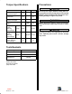
Torque Specifications Fastener Location Precautions Lb. Ft. Lb. In.
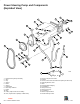
Power Steering Pump and Components (Exploded View) 6 16 22 21 23 3 4 22 20 19 23 1 18 9 17 11 2 12 10 14 5 7 8 15 13 22 23 14 72951 24 1 2 3 4 5 6 7 8 9 101112- Power Steering Pump Assembly Stud Cap Spacer Brace Spacer Lockwasher Bolt, Pump To Brace Pulley Belt O-Ring, High Pressure Hose Fitting Hose, High Pressure (Fittings on Both Ends) 131415161718192021222324- Hose, Pump To Fluid Cooler Clamp Hose, Control Valve To Fluid Cooler (Fitting On One End) Mounting Bracket, Cast Bolt Spacer
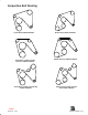
Serpentine Belt Routing ALPHA WITH POWER STEERING ALPHA WITH CLOSED COOLING WITHOUT POWER STEERING ALPHA WITH CLOSED COOLING AND POWER STEERING BRAVO WITH POWER STEERING BRAVO WITHOUT POWER STEERING BRAVO WITH CLOSED COOLING AND POWER STEERING Index 90-823226--1 996 POWER STEERING - 8A-3
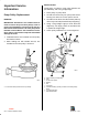
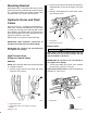
INSTALLATION Important Service Information Install pulley, as follows, using pulley installer tool (91-93656A1), and a long straight edge: 1. Place pulley on pump shaft. Pump Pulley Replacement 2. Thread stud all the way into pump shaft. Place bearing over stud. Do not use spacer from kit. REMOVAL 3. Thread nut onto shaft. Thread tool shaft (and nut) all the way onto stud (threaded into pump pulley).
Testing and Repair Serpentine Belt Adjustment Refer to appropriate MerCruiser Stern Drive Service Manual. 1. Using a 5/8 inch wrench, loosen the nut on the adjustment stud. Checking Pump Fluid Level 2. Place the 5/16 inch deep socket on the hex end of the adjustment stud rotate starboard tensioner until there is 1/4 inch (6 mm) deflection is achieved between the pulleys with the greatest distance between them (this location may be different with various belt configurations).
Pump Assembly IMPORTANT: Be careful to not cross-thread or over-tighten hose fittings. 2. Install mounting hardware and fasteners to retain pump to bracket. (Refer to “Exploded View” for specific details on your engine.) 1. Be certain a new high pressure hose O-ring is present, and install threaded fitting in back of pump assembly. Tighten fitting securely. Connect low pressure hose on back of pump. Tighten hose clamp securely.
Mounting Bracket Mounting bracket is removable after pump (refer to previous instructions) and alternator (refer to Section 4C - “Charging System”) have been removed. See “Exploded View” and “Torque Specifications.” 2. Remove hose where routed and secured (port or starboard side), across top of engine, near valve cover. 3. Remove small fitting from control valve at transom. Remove hose.
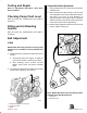
Later Style Control Valve: Torque fittings to 23 lb. ft. (31 N·m) Low Pressure Hose (Cooler-to-Pump) REMOVAL NOTE: Catch fluid that drains from hose, cooler and pump in a suitable container. 1. Loosen hose clamp and remove hose from fluid cooler. c 73786 2. Route hose along valve cover and secure with J-clamp(s) provided. b 3. Be certain a new high pressure hose O-ring is present, and install threaded fitting in back of pump assembly. Tighten fitting securely. Do not cross-thread or over-tighten.
2. Loosen hose clamp and remove hose from back of pump. 2. Using hose clamp, install hose on fluid cooler. Tighten clamp securely. c b a 72588 a b Port Side Mounted Fluid Cooler 72848 a - Fluid Cooler b - Hose Clamp c - Hose a - Hose Clamp b - Hose INSTALLATION 1. Using hose clamp, install new hose on back of pump. Tighten clamp securely. b a 74752 Rear Mounted Fluid Cooler a - Fluid Cooler b - Hose a 3. Fill and air bleed system. Refer to Section 1B “Maintenance” (see “Table of Contents”).
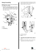
Low Pressure Hose (Control Valve-to-Cooler) REMOVAL NOTE: Catch fluid that drains from hose, cooler and pump in a suitable container. 1. Loosen hose clamp and remove hose from fluid cooler. a 72853 c Port Side Mounted Fluid Cooler Only a - J-Clamps 3. Remove large fitting from control valve at transom. Remove hose.
INSTALLATION 3. Using hose clamp, install hose on fluid cooler. Tighten clamp securely. ! CAUTION Route hoses exactly as shown below. This will help avoid stress on the hose fittings and will help avoid kinks in the hoses. c IMPORTANT: Be careful to not cross-thread or over-tighten hose fittings. 1. Thread large fitting into control valve. Position hose properly (as prior to removal). Earlier Style Control Valve: Torque large fitting to 20-25 lb. ft. (27-34 N·m).
b. Install reservoir mounting bracket with hardware supplied. Priority Valve Kit (79691A1) Information This kit information (in “Installation Instruction” form) is provided to assist personnel when servicing dual installations where both engines are equipped with power steering pumps, coolers, related hardware and hoses, and one transom assembly is equipped with power steering.
IMPORTANT: A two-way valve is required on the reservoir cap for cold weather operation below 40°F (4°C). 6. Secure hoses with Sta-Straps to keep them below reservoir fluid level line and away from heat and moving parts. 3. If required, install two-way valve in reservoir cap by removing vent from cover and replacing it with a two-way check valve.
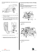
Installing Priority Valve NOTE: Priority valve mounting bracket can be used in various mounting configurations. NOTE: The 90° elbow locations on priority valve are marked with a “T” stamped into the valve. 2. Apply liquid pipe joint sealer to threads and install fittings into priority valve. b a c c a 71404 71403 1. Install priority valve mounting bracket. a. Find a central location that will be accessible for making and checking hose connections. Ensure that location will allow 2 in.
NOTE: Engines with power steering are equipped with a hose that is connected to the power steering fluid cooler. A fitting on the other end of the hose would normally be connected to the power steering control valve. These hoses are not used and are replaced with bulk hose supplied with priority valve kit. from kit) to power steering control valve. Route hose to priority valve, cut hose to length, and connect to fitting on priority valve. Secure with hose clamp. Tighten securely. 4.
8. Install pressure hose (fittings on both ends, from kit) between power steering control valve and large inverted flare fitting on priority valve. (This fitting location is marked with an “S.”) Secure with hose clamp. Tighten securely. 9. Connect No. 1 (starboard) engine pressure hose (from pump) to inverted flare fitting marked by “1” on priority valve. Connect No. 2 (port) pressure hose (from pump) to inverted flare fitting marked by “2” on priority valve. Secure with hose clamps. Tighten securely.
Filling System with Fluid Maintenance 1. Fill pump reservoirs with automatic transmission fluid (ATF) Dexron ll or Dexron lll. Maintenance inspection is the owner’s responsibility and must be performed at the following intervals: 2. Install and tighten pump cap by turning cap clockwise approximately 120 degrees. Normal Service - Every 50 hrs. of operation or 60 days (whichever comes first) Severe Service - Every 25 hrs.
System Flow Diagram 3 a b 2 c c d 5 e f 4 1 d f e 5 Pressure Line Return Line Gravity Feed Line 1 2 3 4 5 - Reservoir Bottle and Bracket Priority Valve and Mounting Bracket Power Steering Control Valve Power Steering Pump Power Steering Fluid Cooler a b c d e f - Pressure Hose (Fitting On Both Ends - Supplied In Kit) Return Hose (Fitting On One End - Supplied In Kit) Return Hose From Pump (Cut From Bulk Hose Supplied) Pressure Hose From Pump Return Hose From Pump Gravity Feed Hose (Cut From
THIS PAGE IS INTENTIONALLY BLANK TO ALLOW FOR CORRECTIONS OR ADDITIONS AT A LATER DATE Index 90-823226--1 996 POWER STEERING - 8A-19