
User's Manual


10
DVI INPUTDVI INPUT
S-VIDEOS-VIDEOOPTICALOPTICAL
AUDIO INPUTAUDIO INPUT
AUDIO INPUT
AUDIO
R L
COMPONENT INPUT
(480i/480p/720p/1080i)
Y P
b
P
r
ANTANT. IN
AC INPUTAC INPUT
RGB INPUTRGB INPUT
AV1
VIDEO
AUDIO
L
R
AV2
VIDEO
AUDIO
L
R
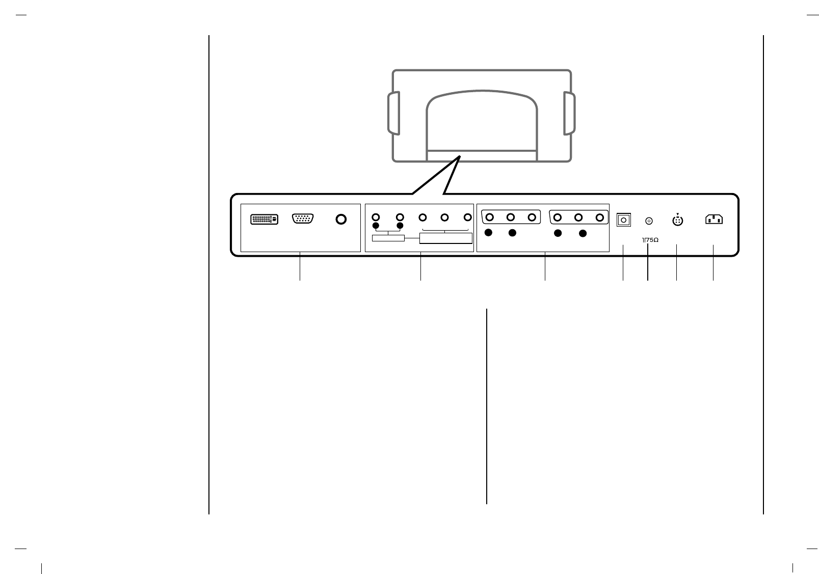
1 2 3 4 5 6 7
1. DVI INPUT / RGB INPUT / AUDIO INPUT SOCKETS
Connect the set output socket of the PERSONAL
COMPUTER to this socket.
2. AUDIO INPUT / COMPONENT INPUT (480i / 480p /
720p / 1080i) SOCKETS
3. AUDIO/VIDEO SOCKET
Connect the audio/video out sockets of the VCR to AV
sockets of the set
4. Digital Audio (OPTICAL)
Connect digital audio from various types of equipment.
Note : In standby mode, these ports will not work.
5. Antenna INPUT
6. S-VIDEO INPUT
connect video out from an S-VIDEO VCR to the S-
VIDEO input.
7. POWER CORD SOCKET
This set operates on an AC power. The voltage is indi-
cated on the Specifications page. Never attempt to
operate the set on DC power.
Location and function of controls
Back panel