
User guide


Page 2
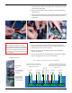
Place the velcro strip between the two adhesive strips on the back of 3.
the battery holder. Make sure the fuzzy side is toward the holder, not
toward the box (left photo).
Remove the two adhesive strips from the back of the battery holder 4.
(middle photo).
Attach the battery holder to the side of the box, with the wires pointing 5.
toward the back of the box (away from you), ush with the standout
(right photo).
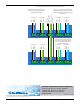
4-port TROLL Net Hub with Internal 9 V Battery
To TROLL #1 To TROLL #2
To Master
(Computer)
To TROLL #3 To TROLL #4
To Level TROLL
- - - - - - - - - - - - - - - -
- - - -
To Level TROLL
To Level TROLL
To Level TROLL
Ground to Level TROLL
RS485(-) to Level TROLL
RS485(+) to Level TROLL
External power wire on Board #1 has
been disconnected to prevent external
charging of the 9V battery.
Positive (+) power wire to slave ports has
been disconnected to prevent the 9V battery
from being used for external power by Level
TROLL devices.
Example: 8-port model
Attach battery
holder.
Disconnect all red
(power) wires from
the boards.
Connect red and
black leads from
battery connector
as shown at right.
REWIRING TO ACCOMMODATE THE BATTERY HOLDER
After securing the battery holder, disconnect all the red wires from 1.
the boards as shown in the 4-port and 8-port diagrams below. Use the
included cap to secure the loose red wires.
Connect the red wire from the battery holder to the circuit board as 2.
shown in the diagram.
Connect the black wire from the battery holder as shown in the diagram. 3.
Keep the existing black wire in place. Do not remove it.
WARNINGS
When using the 9 V battery as a power
source you must disconnect the red power
leads from the instrument boards. Failure to
remove these leads as instructed will cause
the 9 V battery to overcharge, overheat, and
possibly explode.