Operator's Manual TROLL® Link Telemetry System Part number 0058310 Information subject to change without notice. In-Situ, In-Situ logo, Baro Merge, BaroTROLL, HERMIT, iSitu, Pocket-Situ, RDO, RuggedCable, RuggedReader, TROLL, and Win-Situ are trademarks or registered trademarks of In-Situ Inc. © 2014. All rights reserved. 0058312 | Rev.
Copyright © 2007-2013 by In-Situ Inc. All rights reserved. This document contains proprietary information which is protected by copyright. No part of this document may be photocopied, reproduced, or translated to another language without the prior written consent of In-Situ Inc. Mailing and Shipping Address: In-Situ Inc. 221 East Lincoln Avenue Fort Collins, CO 80524 U.S.A. Phone: 970-498-1500 (international & domestic) Fax: 970-498-1598 Internet: www.in-situ.com Support: 800-446-7488 (U.S.A.
Table of Contents 1 2 3 4 5 6 7 8 Overview Unpacking and Inspection Warranty Provisions Obtaining Repair Service Systems Offered SIM Card Changing the Device Address TROLL Link 100 Setup 5 5 6 6 7 7 8 9 Changing Modbus Communication Settings in Win-Situ 5 Determining Your Service Provider Determining SMS Usage Required Items From Your Service Provider Installing the TROLL Link Software Connecting Instruments to the TROLL Link Telemetry System Installing a Battery Connecting the TROLL Link to the PC Confi
11 Field Installation 28 Connecting and Deploying Instruments Installing the TROLL Link Telemetry System Installing a 1 W Solar Panel Installing a 10 or 20 W Solar Panel and External Battery Kit Installing the External Battery Kit Connecting the TROLL LINK to the External Battery Kit Enclosure 28 28 29 30 30 31 12 Turning Off the Modem 13 Troubleshooting 31 32 Troubleshooting - Common Issues Changing Win-Situ Software Device Address and Communication Settings Selecting the Correct COM Port Performing
Overview The TROLL Link Telemetry System provides quick and reliable remote communications using a GSM/GPRS or satellite network. TROLL Link 100 systems require user-configuration of the telemetry, and setting a unique address for each instrument installed in the network. Users must set up a wireless service plan with a cellular service provider or In-Situ Inc. TROLL Link 101 systems are pre-configured by In-Situ Inc., but still require setting a unique address for each instrument installed in the network.
Your TROLL Link Telemetry System was carefully inspected before shipping. Inspect the package for any physical damage sustained during shipment. Notify In-Situ Inc. and file a claim with the carriers involved if there is any damage. Do not attempt to operate the instrument when damage has occurred. Warranty Provisions In-Situ Inc. warrants the TROLL Link Telemetry System for one year from date of shipment by the end user against defects in materials and workmanship under normal operating conditions.
Systems Offered In-Situ Inc. offers three TROLL Link Telemetry Systems: l l l TROLL Link 100—a GSM/GPRS system that uses SMS (text messages), dial-up, or IP connect modes to access data. TROLL Link 101—a GSM/GPRS system that transmits data to the In-Situ Data Center, which can be accessed anywhere you have an internet connection at http://www.isi-data.com/.
1. Align the SIM card so the diagonal cut is facing towards the antenna base. 2. Gently insert the card into the slot and push in fully. Hold the card in place with one finger. 3. While holding the card, slide the lock over the edge of the card. TROLL Link 101 modems are shipped with SIM cards already installed. Changing the Device Address When networking multiple Level TROLL, Aqua TROLL, Rugged TROLL, or RDO PRO Instruments, each device requires a unique device address.
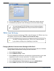
4. Click the check mark to save changes. Click Yes when asked to proceed. 5. Click No when prompted to save the changes as the new default settings. You must change Win-Situ Software communication settings to match the device address next time you connect the instrument. See page 32. TROLL Link 100 Setup This section describes configuring a TROLL Link 100 System. For TROLL Link 101 or 201 Systems, skip to the section TROLL Link 101 and 201 Setup.
7. Click the check mark. Click Yes when asked to proceed. 8. Click No when prompted to save the changes as the new default settings. You will need to change the Win-Situ communication settings to match these settings the next time you connect your instrument. Determining Your Service Provider TROLL Link 100 systems require a wireless service plan provider. Users must obtain their own cellular GSM/GPRS service plan, either from a third party or from In-Situ.
Data sampling rate / SMS frequency (minutes between samples / messages) Messages per day Messages per month 5 288 8928 10 144 4464 15 96 2976 30 48 1488 60 24 744 120 12 372 180 8 248 240 6 186 360 4 124 480 3 93 720 2 62 1440 1 31 Required Items From Your Service Provider Before proceeding with setup and configuration, ensure you have obtained the following items from your service provider.
l APN Name: ccspbsc095.acfes.org or romcomm.apn l APN User ID: (blank) l APN Password: (blank) Installing the TROLL Link Software 1. Install the TROLL Link Setup Utility and Win-Situ 5 Plus Software to your local hard drive. The software can be installed using the In-Situ software CD or downloaded from www.in-situ.com/TelemetrySoftware 2. Follow the installation wizard prompts for both programs to complete the installations. 3.
Connecting Instruments to the TROLL Link Telemetry System All instruments must be connected to the TROLL Link Telemetry System during configuration to set up messages, alarms, and relays. Instruments are connected using a bulkhead-to-twist-lock connection for a single instrument, or using the TROLL Net Hub for a multiple instrument network. When configuring a multiple instrument network, you must have all instruments connected at the same time to properly set up the system.
6. Name the connection if desired. Ensure COM 1 is selected in the Serial Connection drop-down menu. 7. Check all TROLL addresses that are connected to the TROLL Link Telemetry System in the box under the Other Settings field. If the connection fails, follow the steps below. l l l Ensure the serial cable connections at the TROLL Link unit and at the PC are tight. Check the battery terminal connections. Check the top of the modem to ensure the power light is on.
Option Description Send current readings using SMS Messages Sends an SMS (text) message that has been configured in the Messages Tab. You must select the type of TROLL connected to the TROLL Link with the radio buttons below. Wait for a phone call from Win-Situ 5 Connect to the TROLL Link Telemetry System using Modem Communications (dial-up). Wait for an Internet (TCP/IP) connection from Win-Situ Connect to the TROLL Link Telemetry System using IP (internet) Communications.
Configuring the Message/Wake Schedule The Schedule tab determines time periods throughout the day when the TROLL Link Telemetry System turns on to send SMS messages, or turns on and waits to receive a dial-up or TCP/IP connection from Win-Situ 5 Plus. These time periods are called Message/Wake periods. Message periods occur when the TROLL Link is set to SMS mode, while Wake periods occur when the TROLL Link is set to dial-up or TCP/IP mode. Message/Wake periods may occur several times a day.
-OR3. Enter appropriate values for each time parameter under the Create a Schedule section. • Start Time denotes the time each day that Message/Wake periods begin (e.g., 6:00 AM). • End Time denotes the time each day that Message/Wake periods stop (e.g., 9:00 AM). • Wake Interval denotes how often Message/Wake periods occur (e.g., a 1-hour interval means periods occur at 6:00 AM, 7:00 AM, 8:00AM, 9:00AM). • Wake Duration denotes how long Message/Wake periods last (e.g.
1. Click the Messages tab. 2. Select the appropriate destination for the SMS messages. SMS messages are only sent to one device. Messages sent to an email address require a gateway phone number. Contact your service provider for their gateway phone number. In-Situ service plans provided by AT&T have a gateway phone number of 121. • Select A phone. Enter the destination mobile phone number, and a description (a site name or other information) if desired. -OR• Select An email address.
l Up to 16 messages (80 values) can be transmitted at one time. 8. Click the check mark. 9. Repeat steps 5 - 8 for all other SMS messages. 10. Delete a message by selecting it and clicking Delete to remove it from the list. 11. Click the Load Configuration button. 12. Click Test. 13. The TROLL Link Setup Software prompts you to disconnect. Click the Disconnect button. 14. Wait for the message to be sent to your phone or email address.
Configuring Alarms Configure device status alarms, TROLL Link Telemetry System alarms, the frequency the device scans for alarm conditions, and how you are notified of alarms using the Alarms tab. Device alarms (alarms triggered by a pre-set low or high parameter value) are created using Win-Situ 5 Software. You cannot set device alarm parameters using the TROLL Link Setup Software. Device status alarms, such as Device Error and Low TROLL Battery, do not need to be created in Win-Situ 5.
8. Select where to send alarm messages in the Alarm Notification section. • Select A phone. Enter the destination mobile phone number, and a description if desired (site name or other information). -OR• Select An email address. Enter a gateway phone number, and enter the destination email address. SMS Alarm Messages The TROLL Link Telemetry System sends alarm messages when an alarm or warning condition is satisfied. The alarm message contains the time stamp, and then a series of codes.
1. Click the Discrete I/O tab. 2. Select the Active Discrete Control drop-down menu. • Disabled—Discrete I/O is disabled. Other options are disabled. • Enabled—The discrete is ON when a selected parameter value (set below) is exceeded. • On RS485—The discrete is ON when RS485 is active. Other options are disabled. 3. Select the device that triggers the relay. The Scan Rate is shared with the Alarm Scan Rate. Changing this setting changes the Alarm Scan Rate. 4. Select the parameter that triggers the relay.
TROLL Link 100 Wiring Diagram Number Function Wire 1 DC Com (-) Bulkhead black wire; solar panel black wire 2 Discrete Input 3 Discrete Counter 4 RS485 (+) Bulkhead blue wire 5 RS485 (-) Bulkhead green wire 6 DC (+) Bulkhead red wire; fuse blue wire 7 Pulse Count. (-) 8 Pulse Count. (+) 9 Relay (-) 10 Relay (+) Retrieving Data from the TROLL Link 100 Receiving SMS Messages SMS messages are sent according to the Message/Wake schedule.
1. Open Win-Situ 5 Plus Software. 2. Click No when prompted Connect to device now? 3. Click Preferences. 4. Click Comm Settings... 5. Click the radio button next to Modem Communications. 6. Enter the data phone number. 7. Enter the Device Address of the instrument you intend to connect to (Default 1). 8. Enter the number of Retries (user-defined; 3 is recommended). 9. Enter a Transmission Delay value between 15 and 20. 10. Enter the TROLL Link password, if applicable. 11.
10. Enter the TROLL Link password, if applicable. 11. Ensure the Mode is set to Modbus-ASCII. 12. Click the check mark. 13. Click the connect button in the lower-right corner. 14. Click the Logging tab, click the desired log and click Download 15. Click the disconnect button in the lower-left corner. Stopping SMS Messages The directions below describe turning off SMS messages using a direct serial connection. 1. Follow the steps in the section Connecting the TROLL Link to the PC. 2.
TROLL Link 101 and 201 Setup The TROLL Link 101 and 201 systems connect to the In-Situ Data Center, and arrive pre-configured to your settings. Access the Data Center to view your site. To change settings or learn more about the Data Center, see the In-Situ Data Center section. Connecting the Antenna - TROLL Link 101 Only 1. Screw the antenna and gasket onto the antenna connector, located on the top of the enclosure mounting bracket. Installing a Battery 1.
3. Enter your User ID and Password supplied by In-Situ. Click Login. 4. The Site Index appears. The Site Index displays the site name, most recent message received date, number of devices at the site, and the alarm status. 5. Click a site name to view more data from that site. 6. Select a Device to view more data from that device. If the next transmission interval has not occurred, you should confirm that communication from all devices in the network has been successful. 1.
Field Installation Connecting and Deploying Instruments Ensure data-logging capable instruments have been programmed with a data log before completing the following steps. Refer to the instrument manual for instructions on programming a data log. Ensure alarm conditions have been programmed (if applicable). Ensure all instruments have been properly, uniquely addressed in Win-Situ Software with the correct Modbus settings. Perform the following steps for each instrument.
Installing a 1 W Solar Panel A solar panel must be installed with the communication system. It can be installed on the same pole. 1. Hold the solar panel near the top of the pole. Point the panel towards the equator. Adjust the panel angle for optimum sunlight reception. 2. Thread the U-bolt through the solar panel bracket. Place the smaller bracket over the open ends of the bolt. Use the split-lock washers and nuts to tighten the assembly to the pole. Repeat for any remaining open brackets.
Installing a 10 or 20 W Solar Panel and External Battery Kit Installing the External Battery Kit Install the External Battery Kit enclosure. 1. Hold the enclosure to the pole at the desired elevation. The external battery kit should be installed below the TROLL Link Telemetry enclosure. 2. Place a hose clamp or U-bolt into the two cutouts of the top bracket of the enclosure and around the pole. 3. For hose clamps tighten the clamp until the enclosure does not move.
3. Strip the cable ends to 1.3 cm (0.5 inches). 4. Insert the solar panel cable into the dome connector cap, and then through the enclosure. 5. Connect the black lead (negative) from the solar panel to the screw terminal labeled "SOLAR-". Tighten the screw terminal. 6. Connect the white lead (positive) from the solar panel to the screw terminal labeled "SOLAR+". Tighten the screw terminal. 7. Tighten the dome connector cap to ensure that the port with the cable is watertight.
Troubleshooting Troubleshooting - Common Issues Most issues are resolved by verifying the following items. l l l l l The telemetry battery is fully charged (greater than 10 volts), and is receiving recharge power from the solar panel. The communication settings on each connected instrument are correct. This includes the modbus device address, baud rate, data bits, parity bits, stop bits, communication mode, IP address and port number, and COM port (when connected to a PC).
If the instrument is connected to a networking device (e.g., a TROLL Net Hub) when Reset All Devices is clicked, ALL other instruments connected to the networking device are restored to default settings. Unique addressing for the network is lost. Any device deployed in a network must have the appropriate device communication settings reapplied. Selecting the Correct COM Port If you are using a USB TROLL Com, select the correct COM port by following the steps below.
3. Click Preferences. 4. Click Comm Settings, and then click the Port Number menu. 5. Scroll down to find the correct COM port address. Click the check mark to accept the changes. 6. Click the yellow Connect button in the lower right corner to establish a connection to the instrument. Performing a Power Cycle (Resetting the Modem) - 1 W Solar Improperly cycling power may cause electrical issues. Follow the proper procedure step-by-step to avoid damaging equipment. Procedures vary by solar panel type. 1.
Updating the Firmware - TROLL Link 100 Only Updating the firmware and cycling the power (turning the system off and then turning it back on) resolves some issues. 1. Connect the TROLL Link Telemetry System to your PC. 2. Connect power to the TROLL Link. 3. Launch the TROLL Link Setup Software. 4. Click File, and then click Update Firmware... 5. Ensure the COM shown in the Port drop-down menu is correct. 6. Follow the onscreen instructions. 800-446-7488 35 www.in-situ.
Troubleshooting Table Problem Possible Solution • Ensure the correct COM port is selected. Unable to connect to a TROLL Link 100 to the TROLL Link Setup Software. • Ensure power is connected to the telemetry unit, and then close and reopen the software. • Ensure the serial cable between the PC and the telemetry unit is properly connected. • Ensure the serial cable is functional. An instrument is not displayed in the TROLL Link Setup Software.
Problem Possible Solution • Ensure the correct IP Address is entered. See page 24. • Ensure the correct Port Number is entered. See page 24. • Ensure the correct Device Address is entered. See page 24. Unable to connect the TROLL Link Telemetry System to WinSitu 5 Plus Software in TCP/IP mode. • Ensure the communication mode is set to ASCII. See page 9. • Ensure the Transmission Delay is set between 15 to 20 seconds. See page 24. • Ensure all communication settings on the instrument are correct.
Maintenance Fuse Replacement Two fuses are located on the left edge inside of the enclosure. The left fuse connects to the internal battery, the right fuse connects to the charger/external power. The fuses are 2 amp, time-delay, speed-type fuses rated for 250 VAC. Replace as needed. Enclosure Desiccant It is extremely important to use a properly-sized desiccant for your deployment, and to change desiccant before the entire volume has turned pink.
Specifications Enclosure Materials Fiberglass Dimensions 29.21 x 25.40 x 12.7 cm (11.5 x 10 x 5 in.) Operating Temperature Range - 40 to 60°C (- 40 to 140°F) NEMA Rating 4X Weight (typical) 6.8 kg (15 lbs) with solar panel and battery Pole Mount 60 mm (2.375 in.) diameter Power Supply Solar Panel 1, 10, or 20 W Battery 12 V, 7 Amp-hour 800-446-7488 39 www.in-situ.
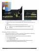
In-Situ Data Center In-Situ Data Center Accessing the Data Center Note that it may take up to an hour for data to be transmitted to the Data Center, depending on the data service package you have. 1. Open a Web browser. 2. Enter the URL: http://www.isi-data.com 3. Enter your User ID and Password supplied by In-Situ. Click Login. 4. The Site Index appears. The Site Index displays the site name, most recent message received date, number of devices at the site, and the alarm status. 5.
Site Index The Site Index appears when you first log in to the Data Center. Number 800-446-7488 Description 1 Create and manage data reports that include all devices. 2 Create and manage users and user privileges. 3 Configure sites, devices, graphs, and notifications. 4 Configure contact information and device alarms. 5 Click on a site name to retrieve the site summary. 6 View the date and time of the most recent message received. 7 View the number of devices at the site.
Site Summary The Site Summary screen appears when you click on a specific site. Number 800-446-7488 Description 1 Click to view the Site Summary Graph. 2 Click a device to view device details. 42 www.in-situ.
Site Management The Site Management/Configuration screen appears when you click Manage Site. Number Description 1 Click to add data points to the top device on the site (see below). 2 Click to assign and update devices on the site (see below). 3 Click a device to manage the device. 4 Add a new site, delete a site, and manage the images displayed. 1 - Site Index (see image below) 800-446-7488 43 www.in-situ.
l Click Edit to edit parameters. l Click the green arrows to adjust the order of parameters. l Click the red X to delete parameters. Click the Add Point button to add a new summary data point. 2 - Assign Devices (not shown) l Check or clear the box to assign a device. l Click Update Site Devices. 800-446-7488 44 www.in-situ.
Device Detail The Device Detail screen appears when you click on a specific device. Number 800-446-7488 Description 1 Click to select the data timeframe from the drop-down list. 2 Click the blue labels to select the view or export the data to CSV. 3 Click the link to create and manage device specific reports. 45 www.in-situ.
Manage Device The Manage Device screen appears when you click a specific device from the Site Management screen. Number Description 1 Edit device settings. Description is used by In-Situ to identify the system and should not be changed. 2 Click to edit registers or copy existing registers to another device. Click the Update Device button to save changes to the device. 800-446-7488 46 www.in-situ.
User Management Create User 1. Click Create New User. 2. Enter the new user data in the fields shown. 3. Click the Set as site admin check box if the user requires site administration privileges. 4. Click Create User. Manage Users 1. Click Edit to edit user settings. 2. Click Reset Password to reset a user password. 3. Click the red X to delete a user. 800-446-7488 47 www.in-situ.
800-446-7488 48 www.in-situ.
Configuring the TROLL Link Telemetry System Using Over-Air Commands TROLL Link Telemetry System 101 and 201 models are pre-configured to the correct instrument types, requested parameters, and transmission interval prior to shipping. Altering this configuration is possible, but not recommended. Increasing the number of parameters or the transmission interval may result in data overage charges if the increased data transmission exceeds the purchased data plan. Consult In-Situ Inc.
Available message intervals are displayed based on your data service plan. 5. Click the arrow next to Sample Rate/Hyper mode, and select None. 6. Click the arrow next to Message Holding, and select No Holding. 7. Click the Send Config button at the bottom of the parameter list to finalize the configuration. All other instruments are updated to transmit using these settings. 800-446-7488 50 www.in-situ.