Operator's Manual SMARTROLL™ MP Handheld Instrument Information subject to change without notice. In-Situ, In-Situ logo, Baro Merge, BaroTROLL, HERMIT, iSitu, Pocket-Situ, RDO, RuggedCable, RuggedReader, TROLL, and Win-Situ are trademarks or registered trademarks of In-Situ Inc. © 2013. All rights reserved. 0099172 | Rev.
Copyright © 2013 by In-Situ Inc. All rights reserved. This document contains proprietary information which is protected by copyright. No part of this document may be photocopied, reproduced, or translated to another language without the prior written consent of In-Situ Inc. Mailing and Shipping Address: In-Situ Inc. 221 East Lincoln Avenue Fort Collins, CO 80524 U.S.A. Phone: 970-498-1500 (international & domestic) Fax: 970-498-1598 Internet: www.in-situ.com Support: 800-446-7488 (U.S.A.
Table of Contents 1 Introduction 6 Scope Serial Number Location 6 6 2 Safety 3 General Specifications 4 Sensor Specifications 6 7 8 Level, Depth, Pressure Sensor Specifications Barometric Pressure Sensor Specifications (Battery Pack) Conductivity Sensor Specifications Dissolved Oxygen RDO Fast Cap (Optical Sensor) Specifications ORP Sensor Specifications pH Sensor Specifications Air Temperature Sensor Specifications (Battery Pack) Sample Temperature Sensor Specifications (Probe) 8 8 9 9 10 10 10 11
11 iSitu Data 29 About Data Record Data View an Individual Reading View and Email Data from the Selected Site View, Email, or Delete Data from Any Site Emailing Data From Different Screens in iSitu Emailing from the Data screen Emailing from the Logs screen Emailing from the Readings screen Emailing from the Data Details screen Transfer Data to a Computer Delete all Logs by Site Restore Data 12 iSitu Sensor Calibration 29 29 29 30 32 34 34 34 35 35 35 35 36 37 About Calibration Calibrate Multiple Sens
User-Serviceable Parts O-rings RDO Fast Sensor Cap Replacement pH/ORP Sensor Replacement Instrument Storage Cleaning the pH/ORP Sensor Remove Crystalline Deposits Remove Oily or Greasy Residue Remove Protein-Like Material or Slimy Film Cleaning the RDO Sensor Clean the Sensor Cap Clean the Optical Window Cleaning the Conductivity Sensor Cleaning Procedure 1 Cleaning Procedure 2 Cleaning Procedure 3 Cleaning Procedure 4 15 Declaration of Conformity 67 67 67 67 67 68 68 68 69 69 69 69 69 70 70 70 70 71 5
Introduction This manual is intended to describe the characteristics, operation, calibration, and maintenance of the SmarTROLL™ MP Instrument. Scope This manual covers the following information.
General Specifications Operating temperature -5 to 50° C (23 to 122° F) Storage temperature -40 to 65° C (-40 to 149° F) Dimensions 4.7 cm (1.85 in.) OD x 26.9 cm (10.6 in.) with restrictor installed (does not include connector) Weight 694 g (1.53 lbs) Wetted materials PVC, 316 stainless steel, titanium, Acetal, Viton®, PC/PMMA Environmental rating IP68 with all sensors and cable attached. IP67 with sensors removed and cable detached.
Sensor Specifications Level, Depth, Pressure Sensor Specifications Accuracy Typical ±0.1% FS @ 15° C; ±0.3% FS max. from 0 to 50° C Range 76 m (250 ft); absolute (non-vented) Resolution ±0.01% FS or better Sensor Type Fixed Response Time Instantaneous in thermal equilibrium Units of Measure Pressure: psi, kPa, bar, mbar, mmHg, inHg Level: mm, cm, m, in, ft Methodology Piezoresistive; ceramic Barometric Pressure Sensor Specifications (Battery Pack) Accuracy ±3 mbar max.
Conductivity Sensor Specifications Accuracy Typical ±0.5% + 1 μS/cm; ±1% max. Range 5 to 100,000 μS/cm Resolution 0.1 μS/cm Sensor Type Fixed Response Time Instantaneous in thermal equilibrium Units of Measure Actual conductivity (μS/cm, mS/cm) Specific conductivity (μS/cm, mS/cm) Salinity (PSU) Total dissolved solids (ppt, ppm) Resistivity (Ohms-cm) Density (g/cm3) Methodology Std. Methods 2510 EPA 120.1 Dissolved Oxygen RDO Fast Cap (Optical Sensor) Specifications Accuracy ±0.1 mg/L; ±0.
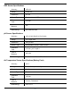
ORP Sensor Specifications Accuracy ±5.0 mV Range ±1400 mV Resolution 0.1 mV Sensor Type Replaceable pH/ORP combo sensor Response Time <15 sec. Units of Measure mV Methodology Std. Methods 2580 pH Sensor Specifications Accuracy ±0.1 pH unit from 0 to 12 pH units Range 0 to 14 pH units Resolution 0.01 pH unit Sensor Type Replaceable pH/ORP combo sensor Response Time <15 sec., pH 7 to pH 4 Units of Measure pH units Methodology Std. Methods 4500-H+ EPA 150.
Sample Temperature Sensor Specifications (Probe) Accuracy ±0.1° C Range -5 to 50° C (23 to 122° F) Resolution 0.01° C or better Sensor Type Fixed Response Time <30 sec. Units of Measure Celsius, Fahrenheit Methodology EPA 170.
Battery Pack Specifications Battery Type Four 1.5V AA lithium or alkaline batteries Operating temperature -5 to 50° C (23 to 122° F); 95% relative humidity, noncondensing Storage temperature -40 to 65° C (-40 to 149° F); 95% relative humidity, noncondensing Dimensions & weight 9.5 x 7.6 x 5.7 cm (3.75 x 3 x 2.25 in.) (H x D x W). Weight: 165 g (5.
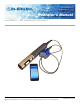
Instrument Overview Instrument Description The smarTROLL™ MP Handheld Instrument is comprised of a mobile display, battery pack, cable, and multiparameter water quality probe. The optical Rugged Dissolved Oxygen (RDO®), conductivity, pressure, and temperature sensors are integrated into the probe. The pH/ORP and the RDO Sensor Cap are replaceable. System Components The system includes the following components.
Probe Dimensions with Restrictor On Total length with connector 281.81 mm (11.1 in.) Total length without connector 269.11 mm (10.6 in.) Restrictor length 118.24 mm (4.7 in.) Diameter 47 mm (1.85 in.) Probe Dimensions with Restrictor Off Sensor length 81.09 mm (3.2 in.
Sensors Sensors include optical RDO (Rugged Dissolved Oxygen), pH/ORP, conductivity, pressure, and temperature.
Probe Setup The probe is shipped with a storage plug and protective dust caps in place. 1 Dust cap protector on the RDO Sensor. (Install the RDO Cap before deploying the instrument.) 2 pH/ORP storage plug. (Remove the storage plug and install the pH/ORP sensor before deploying the instrument.) Install the Batteries The 4 AA batteries that are shipped with the battery pack are likely to last for 80 hours of continuous use.
1. Twist the cable connector counterclockwise to remove the cable from the battery pack. 2. Slide the lever on the battery compartment to release the cover. 3. Install the 4 AA batteries according to the +/- indicators engraved on the outside cover. 4. Close the cover and slide the lever to lock the compartment.
Installing the Sensors 1. Twist the restrictor off the probe. 2. Locate the RDO Sensor Cap container and remove the cap. 3. Remove the dust cap from the RDO Sensor. 4. Align the flat edge of the RDO Sensor with the slotted edge of the RDO Cap and press the cap into position. Push until the cap is firmly in place.
Important: Avoid touching the sensor lens and the sensing material on the top of the cap. 5. Remove the orange plug from the pH/ORP port. 6. Remove the pH/ORP sensor from the storage bottle. Keep the bottle for future sensor storage. 7. Use the alignment marks to properly align the pH/ORP sensor with the port connection, and press firmly into place. Push until the sensor is completely inserted into the port. 8. Twist the restrictor onto the probe. 9.
iSitu Overview About the iSitu App The iSitu App is the user interface and control application for In-Situ Inc. handheld water quality instruments. You can use iSitu on the Apple iPod Touch, and iPhone for up to five devices per purchased license. iSitu allows you to accomplish the following tasks. l View live readings that update every 10 seconds. l Change parameters and units. l Record data. l Email data in spreadsheet format. l Transfer data from mobile device to a computer.
4. Turn Bluetooth on. 5. Press the Home button (round button on the mobile device frame) to show all apps. 6. Tap the iSitu icon to open the iSitu App. 7. If you are prompted to allow iSitu to use your current locations, tap OK. If you allow iSitu to use your current locations it will enable the mapping feature for site setup. If you select Don't Allow, you can change the setting later. See Settings > Privacy Settings > Location Services.
8. Live readings appear on screen.
Live Readings Screen The Live Readings screen is also referred to as the Home screen. If you touch the Home icon within the app you will return here. Live readings update every 10 seconds.
Change Parameters and Units 1. From the Home screen, tap any parameter field. 2. Swipe the left side of the parameter pick wheel to find the appropriate parameter. 3. Swipe the right side of the parameter pick wheel to select the appropriate unit. 4. Tap the Set button to set the parameter and unit selection.
iSitu Sites About Sites A site represents the physical location at which the instrument collects data. For example, you can create a site to represent a lake, gauging station, well, tank, number, or nearby landmark. If you do not set up a site, your data will be associated with Default Site. The site name is displayed at the top of the Live Readings screen. Tap the Sites button to select or edit an existing site, or to create a new site. Create a New Site 1.
3. Tap the New Site button. The Site Details screen appears. 4. Tap the Name field. Type the name for the new site and tap Return. 5. To add a description, tap the Description field. Type a description and tap Return. A description is optional. 6. To take a site photo, tap the Camera button, tap the camera icon to take a new photo, tap the Use button. A site photo is optional. 7. To select an existing photo, tap the Album button, tap Cameral Roll, tap an existing photo.
8. To locate your site with Maps or GPS, tap the GPS button and your current location is automatically associated with the site. You can also enter GPS coordinates, or tap and hold on the map to select a location. Location Services must be turned on for an accurate location to display on the map. See Settings > Location and Security. 9. Tap the Save button. 10. Tap the Set button next to the site you created. Now you are ready to record data associated with the selected site.
Delete a Site 1. Tap the Sites button. 2. Locate the site you intend to delete. 3. Tap the circle associated with the site. 4. Tap the Delete button. This procedure sends the site to the trash where you can choose to completely delete it, or restore the site. You cannot delete the default site. Restore a Site 1. It is possible to restore a deleted site. 2. From the Home screen, tap the Sites button. 3. Tap the Restore From Garbage Can icon. 4. Tap the site you intend to restore. 5. Tap the Restore button.
iSitu Data About Data iSitu allows you to view real-time readings, record readings in ten-second intervals, email data, store data to the mobile device, and transfer data from the mobile device to a PC. Record Data 1. Tap the Record button on the Live Readings screen to record data. The number on the stopwatch icon represents how many 10-second data intervals have transpired. 2. To stop recording, tap Stop. 3. Now you can email the data or download it to a computer.
1. To view an individual reading, tap the Action icon. 2. Tap View Last Reading. 3. The most recent data in the last ten-second interval appears. Tap the Home icon to return to the Live Readings screen or tap the Envelope icon to email the data. View and Email Data from the Selected Site After you have recorded data, you can email the data as a CSV file that can be opened with common spreadsheet software. Make sure the email feature is enabled on the mobile device.
1. Tap the Action icon. 2. Tap View Log List. This shows a list for only the selected site. 3. To select all logs in the list, tap the All/None button, or to select individual logs, tap them separately.
4. Tap the Envelope icon. 5. An email form appears with the logs that were selected attached. 6. Enter an email address in the To: field. 7. Tap the Send button. You can also transfer data to a computer using iTunes. View, Email, or Delete Data from Any Site After you have recorded data, you can email the data as a CSV file that can be opened with common spreadsheet software. Make sure the email feature is enabled on the mobile device. See Settings > Mail, Contacts, Calendars > Add Account.
1. Tap the Data icon. 2. The Data screen displays a list of sites and the number of data logs within each site. Tap the site that contains the data you want to view, email or delete. The selection circle turns red and the View, and Delete, buttons become active. 3. Tap the View button. 4. The list of logs associated with that site appears. Tap the log you want to view. The selection circle turns red and the View and Delete buttons become active. The Envelope icon also becomes active.
5. Tap the View button. 6. The list of readings within the log appears. Tap the reading you want to view. The selection circle turns red and the View button becomes active. 7. Tap the View button. The data for an individual reading appears. Emailing Data From Different Screens in iSitu Emailing from the Data screen Select one or more sites and email all logs associated with the selected sites. Emailing from the Logs screen Select one or more logs (from a single site) and email the selected logs.
Emailing from the Readings screen Select one or more readings (from a single log) and email them as one file. The file name will be appended with the word "reading." Emailing from the Data Details screen Emailing from the Data Details view will email all readings in that log Transfer Data to a Computer 1. Connect the mobile device to a computer with iTunes installed. 2. Click on the Apple device icon next to the eject button. 3. Click the word Apps near the top of the screen. 4.
This procedure sends the logs to the trash where you can choose to completely delete them or restore the logs. Restore Data It is possible to restore deleted logs. 1. Tap the Data icon. 2. Tap the Restore from Garbage Can icon. 3. The contents of the Trash Can are displayed. 4. Tap theAll/None button, or tap the individual logs you want to restore. 5. Tap the Restore button. If you want to permanently delete data from the Trash Can, tap the Delete button.
iSitu Sensor Calibration About Calibration Tap the Calibration icon available for calibration. in the iSitu App to access a list of sensors that are Calibrate Multiple Sensors with Quick-Cal Solution 1. Tap the Calibration icon calibration. to access a list of sensors that are available for 2. Tap Quick-Cal. 3. The conductivity, pH, and ORP sensors are automatically selected. Tap the green check mark next to a sensor if you want to exclude it from the quick calibration.
The dissolved oxygen sensor cannot be calibrated using the Quick-Cal procedure. 4. Tap OK. 5. Fill the calibration cup to the fill line with Quick-Cal solution. 6. Place the instrument into the calibration cup, and tap Start. 7. When the calibration is stable, tap the Accept button.
8. Rinse the sensors with DI water. Calibrate the Rugged Dissolved Oxygen Sensor The RDO sensor requires very little maintenance. The zero oxygen calibration is optional. 1. Tap the Calibration icon . 2. Tap RDO Sensor. 3. Select the method by which you intend to calibrate the sensor. This example demonstrates a two-point calibration. Tap 100% and 0% Saturation.
4. Place a water-saturated sponge in the bottom of the calibration cup. Place the instrument into the calibration cup, and tap Start. The calibration cup must be vented to barometric pressure. If you are using the calibration cup pictured below, make sure the vented cap is installed. If you are using the twist-on storage cup, set the instrument in the cup, but do not twist it into place. 5. When the calibration is stable, tap the Accept button.
6. Remove the sponge and add fresh sodium sulfite solution to the fill line. Place the instrument into the calibration cup, and tap Start. 7. When the calibration is stable, tap the Accept button.
8. To view the calibration report, tap View Report. 9. Rinse the sensors thoroughly with DI water. Calibrate the Conductivity Sensor 1. Tap the Calibration icon calibration. to access a list of sensors that are available for 2. Tap Conductivity Sensor. 3.
4. Make sure the vented cap is installed on the calibration cup. Fill the cup to the fill line with calibration standard. Place the instrument into the calibration cup, and tap Start. 5. iSitu automatically detects the calibration standard.
If your calibration standard references 20° C, tap the Thermometer icon and change the reference temperature. 6. Once the calibration is stable, tap the Accept button. 7. To view the calibration report, tap View Report. 8. Rinse the sensors with DI water. Calibrate the Depth Sensor Zero in Air 1. Tap the Calibration icon calibration. to access a list of sensors that are available for 2. Tap Depth Sensor. 3. Tap Zero in Air.
Do not perform a "Zero in Air" calibration if a Depth reference is already set because it will result in a faulty calibration. To clear a Depth reference, tap Restore Defaults. 4. Ensure that the pressure sensor is exposed to air and is not submerged in liquid. 5. Tap the Start button. 6. When the calibration is stable, tap the Accept button. Setting the Depth Reference 1. Tap the Calibration icon calibration. to access a list of sensors that are available for 2. Tap Depth Sensor. 3.
4. Place the instrument in the water at a known depth, and tap the Start button. 5. Tap the Reference Value field and enter the value of the known depth reference.
A depth reference applies an offset equal to the distance from the pressure sensor to a desired location, such as the bottom of the probe, so that the depth reading is reported from the desired location, rather than from the location of the pressure sensor. 1 Pressure sensor 2 Example of a Depth reference setting 6. When the calibration is stable, tap the Accept button. Calibrate the pH Sensor 1. Tap the Calibration icon calibration. to access a list of sensors that are available for 2.
4. Make sure the vented cap is installed on the calibration cup. Fill the cup to the fill line with the first calibration buffer. Place the instrument into the calibration cup, and tap Start. 5. When the calibration is stable, tap the Accept button.
6. Fill the cup to the fill line with the second calibration buffer. Place the instrument into the calibration cup, and tap Start. 7. When the calibration is stable, tap the Accept button. 8. To view the calibration report, tap View Report.
Calibrate the ORP Sensor 1. Tap the Calibration icon calibration. to access a list of sensors that are available for 2. Tap ORP Sensor. 3. Tap 1-Point Calibration 4. Make sure the vented cap is installed on the calibration cup. Fill the cup to the fill line with calibration standard. Place the instrument into the calibration cup, and tap Start.
5. When the calibration is stable, tap the Accept button. 6. To view the calibration report, tap View Report.
Low-Flow Pump Testing Low-Flow Sampling with SMARTROLL™ MP Instrument Low-Flow sampling allows you to automate the collection of well and pumping information, monitor and record the stabilization of key water quality parameters, and automatically generate sample reports that conform to federal and regional regulations. You can set up a template in the office and email it to a technician, or the setup can be done entirely in the field. You need the following equipment.
4. You are prompted to enter your iTunes information. The Low-Flow App will be accessible the next time you tap the Gear icon. Create a Low-Flow Template from the Desktop You can create a Low-Flow template from a desktop or laptop computer and email it to technicians in the field. This Windows® software application is designed to work in conjunction with the iSitu mobile App and the SMARTROLL MP Instrument. 1. Open the Low-Flow software from within Win-Situ 5.
3. Click Create New Template, and click the right arrow button. The Project screen appears. 4. Enter project information and click the right arrow button. The Units screen appears. 5. If necessary, select a parameter and then click the drop-down box to select units. 6. Click the right arrow button. The Well Information screen appears.
7. When you click on a field, the corresponding area of the well diagram is highlighted. Enter the well information. 8. Click the right arrow button. The Stabilization Parameters screen appears. 9. The default stabilization criteria is shown. A selected percentage checkbox indicates that the stabilization criterion for the parameter is based on percentage rather than an absolute value. 10. Edit the information if necessary, and click the right arrow button.
11. Enter the pump information. The total system volume is calculated using the internal pump volume, the tubing inner diameter, and the tubing length. 12. Click the right arrow button. The Purging Information screen appears. 13. Enter the pumping rate you intend to use during the test. 14. Enter the sampling rate you intend to use, or select Auto calculate sample rate using system purge time if you want the software to assign a sample rate. 15.
Email Low-Flow Template to an iPod or iPhone 1. Low-Flow templates are by default saved to your computer in My Documents/LowFlow Templates. 2. One way to email a template is to open the LowFlow Templates folder and rightclick on the template you want to email. 3. Select Send to and select Mail recipient. A new email will open with the template attached. 4. Send the email to a device that has email enabled. Load the Template into the iSitu App 1. Open the email on the mobile device. 2.
4. Tap the iSitu icon. The iSitu app opens with the template loaded. If you would like to save the template to the device, tap the Save button. You can swipe through the screens and edit information before you save changes to the template.
Set up a Low Flow Test From a Template 1. Tap the Gear icon to access the Low-Flow section of the App. 2. The Project screen appears. 3. Tap the Template button. A list of all saved templates appears.
4. Tap on the template you intend to load, and tap the Load button. Set up a Low-Flow Test without a Template 1. Tap the Gear icon to access Low-Flow and tap Launch. 2. The Project screen appears.
3. Tap a text-entry field to open the keyboard. 4. Enter the project information. Tap the Return button on the keyboard to close the keyboard. 5. Tap the Next button to continue to the Units screen. 6. If you want to change units, tap the units button and select a different value. 7. Tap the Next button to continue to the Well screen.
8. Enter the well information. 9. Tap the Next button to continue to the Stabilization screen. 10. A green checkmark indicates that the stabilization criterion for the parameter is based on percentage rather than an absolute value. Tap a gray box to change from absolute to percentage. 11. Tap the Next button to continue to the Pump screen.
12. Enter the pump information. The total system volume is calculated using the internal pump volume, the tubing inner diameter, and the tubing length. 13. Tap the Next button to continue to the Purge screen. 14. Enter the pumping rate you intend to use during the test. 15. Enter the sampling rate you intend to use, or select Auto Calculate Samle Rate if you want the software to assign a sample rate. 16. Enter an estimate of the drawdown you expect during the testing.
17. If you would like to save the test set up information as a template to use again later, tap the Save button. You can save it using the default name, or tap the field and enter a new name. Install the Pump 1. Determine the static water level. 2. Install the pump in the well. 3. Start the pump and determine the optimum final pumping rate and final stabilized drawdown from static water level. This can be calculated using a graduated cylinder, stopwatch, and water level tape. Prepare the Flow Cell 1.
Start a Low-Flow Test 1. After you have entered the setup information, installed the pump, and set up the flow cell you are ready to start the Low-Flow test. 2. From the Purge screen tap the Start button. 3. The test begins and the sample rate countdown is displayed on screen. The parameters appear after the first countdown is complete. 4. When you are satisfied with the stability of the test, tap the Accept button. 5. Enter the final values for drawdown, pumping rate, and total volume pumped. 6.
5. Click on a file and drag it to your desktop.
Care and Maintenance Maintenance Schedule For best results, send the instrument to the manufacturer for factory calibration every 12 to 18 months. User-Serviceable Parts The user-serviceable parts on the instrument include the O-rings, the pH/ORP sensor, and the RDO Sensor Cap. O-rings The instrument has several O-rings that can be maintained by the user in order to keep moisture from entering the instrument and damaging the electronics.
To store the probe for more than a week, perform the following procedure. 1. Remove the pH/ORP sensor and place the orange pH port plug into the empty pH/ORP port to prevent any humidity from entering the probe. 2. Locate the sensor storage bottle in which the pH sensor was originally shipped. 3. Open the bottle and remove the O-ring. 4. Moisten the sponge inside the bottle with either a pH storage solution or a pH 4 solution. 5.
Remove Protein-Like Material or Slimy Film l l Clean the sensor with warm water and mild soap. Soak the sensor in 0.1M HCI solution for 10 minutes and then rinse with deionized water. Note: After performing any of these cleaning methods, rinse the sensor with water and then soak overnight in pH 4 buffer. Cleaning the RDO Sensor Clean the Sensor Cap 1. Leave the cap on the sensor. 2. Rinse the sensor with clean water from a squirt bottle or spray bottle. 3.
Cleaning Procedure 1 Avoid damaging the plastic material of the conductivity cell. Gently scrub the conductivity cell with a soft swab and mild soap such as a dilute solution of dish detergent. The probe is shipped with polyurethane foam swabs for this purpose. You can also achieve good results using a gentle back-and-forth motion with a thin cotton pipe cleaner. If debris is still present, continue to Cleaning Procedure 2. If the sensor is clean, skip to the last step.
Declaration of Conformity 71