Operator's Manual RDO® PRO-X Process Optical Dissolved Oxygen Probe Information subject to change without notice. In-Situ, In-Situ logo, Baro Merge, BaroTROLL, HERMIT, iSitu, Pocket-Situ, RDO, RuggedCable, RuggedReader, TROLL, and Win-Situ are trademarks or registered trademarks of In-Situ Inc. © 2013. All rights reserved. 0088692 | Rev.
Copyright © 2008-2013 by In-Situ Inc. All rights reserved. This document contains proprietary information which is protected by copyright. No part of this document may be photocopied, reproduced, or translated to another language without the prior written consent of In-Situ Inc. In-Situ Inc. makes no warranty of any kind with regard to this material, including, but not limited to, its fitness for a particular application.
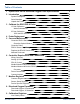
Table of Contents 1 Optical RDO PRO-X Dissolved Oxygen Probe Specifications 2 Introduction System Description Serial Numbers Unpack the Probe 5 6 6 7 7 3 Calibrate the RDO PRO-X Probe 9 1-Point Calibration Water-Saturated Air 2-Point Calibration 100% and 0% Saturation 9 9 10 10 4 Probe Deployment 5 Care and Maintenance 11 12 Clean the RDO-X Sensor Cap Clean the Optical Window Clean the Probe RDO-X Sensor Cap Storage Replace the RDO-X Sensor Cap Maintain Desiccant 12 12 12 12 12 13 6 Controller Req
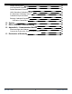
Default Salinity Value 24 24 24 24 25 25 25 26 Live Barometric Pressure Default Barometric Pressure 100% Saturation Calibration Values 0% Saturation Calibration Values Calibration Slope and Offset Entering Calibration Registers Calibration Calculations 10 Service 11 RDO-X Software Troubleshooting 12 Appendix A - Communication Device Install and Open the Software Connect the Probe to the Communication Device 13 Declaration of Similarity 800-446-7488 27 27 28 28 28 29 4 www.in-situ.
Optical RDO PRO-X Dissolved Oxygen Probe Specifications Optical RDO PRO-X Dissolved Oxygen Probe Sensor Type Optical (luminescent) dissolved oxygen sensor Range: 0 to 50 mg/L concentration Accuracy: ±0.1 mg/L, 0 to 8 mg/L RDO PRO-X Probe ±0.2 mg/L, 8 to 20 mg/L ±10% of reading, 20 to 50 mg/L Resolution: 0.
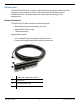
Introduction The RDO PRO-X Probe is a rugged, reliable instrument designed to deliver accurate dissolved oxygen (DO) data across a wide measurement range and to reduce maintenance costs. The probe features the latest optical technology for DO measurement. System Description The RDO PRO-X system consists of the following items.
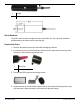
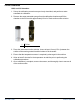
1 Probe 2 Cable end, twist-lock connector and RuggedCable System Serial Numbers The probe serial number is engraved on the side of the unit. The cap serial number is programmed on the memory chip inside the cap. Unpack the Probe 1. Remove the probe from the box and other packaging materials. 2. Unscrew the nose cone from the probe and remove the red protective dust cap from the sensor. Save the dust cap for later use. 1 Dust cap 2 Nose cone 3. Remove the RDO cap from the storage sleeve. 4.
1 Alignment arrow on cap 2 Cap installed over lens 3 Nose cone Do not allow moisture or atmospheric humidity inside the cap. Keep the cap in its sealed package until you are ready to install it. Install promptly. Ensure that O-ring grooves are dry and that the Oring is not rolled or pinched inside the cap. The typical cap lifetime is two years after the first reading has been taken. 5. Reattach the nose cone. 800-446-7488 8 www.in-situ.
Calibrate the RDO PRO-X Probe Calibrate the sensor with the Comm Kit Software and the RDO PRO Communication Device, or calibrate the sensor directly with your controller. 1-Point Calibration Water-Saturated Air 1. Remove the storage cap from the top of the calibration chamber and replace it with the vented calibration cap. 1 Storage cap 2 Vented calibration cap Figure 6.1 Storage cap and vented calibration cap shown together 2.
2-Point Calibration 100% and 0% Saturation 1. Set up the calibration procedure as previously described, and perform a watersaturated air calibration. 2. Remove the water-saturated sponge from the calibration chamber and fill the chamber to the fill line with approximately 60 mL of fresh sodium sulfite solution. 1 Fill line 2 Temperature sensor 2. Place the instrument into the solution. Leave at least 13 mm (0.5 in.) between the surface of the sensing material and the bottom of the chamber. 3.
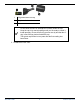
Probe Deployment The cable end of the RDO PRO-X Probe is internally threaded (1¼ – 11½ NPT) and can be attached to a male threaded pipe. When deployed, make sure that the nose cone and thermistor are completely submerged. 1 10 m cable attached 2 Twist-lock connector 3 1 1/4 NPT threading 800-446-7488 11 www.in-situ.
Care and Maintenance Clean the RDO-X Sensor Cap 1. The cap and nose cone must remain on the probe. 2. Rinse the sensor with clean water from a squirt bottle or spray bottle. 3. Gently wipe with a soft-bristled brush or soft cloth if biofouling is present. Use Alconox to remove grease. 4. If extensive fouling or mineral build-up is present, soak the cap end in vinegar for 15 minutes, then soak in deionized (DI) water for 15 minutes. Do not use organic solvents—they will damage the sensing element.
3. Pull the used RDO cap off of the sensor, without twisting. 4. Remove the existing O-rings from the sensor. Ensure that there is no moisture in the O-ring grooves. Do not touch or clean the lens with anything other than the supplied lens wipe. 5. Use your finger to apply a very light layer of silicone-based lubricant around the Oring grooves. 6. Place the O-rings on the sensor. Apply another thin layer of lubricant to the O-rings and grooves. Note: Do not transfer grease to the lens or sensor pins. 7.
Controller Requirements and Connections The RDO PRO-X Probe may be connected to a controller or logger for communication via the following options. l Analog (4-20 mA) provides a configurable 4-20 mA current loop output l SDI-12 l RS485 Modbus l RS232 to Modbus Wiring Overview Refer to diagrams on the following pages. Trim and insulate unused wires. The shielded wire should be connected to a chassis ground or earth ground. The inside of the controller must be kept free of moisture and humidity.
Analog (4-20 mA) 3-wire Signal Color Ground/Return Black External Power (12-36 VDC) Red 4-20 mA Brown Cable length must not exceed 1219 m (4000 ft.) Analog signal must be enabled in Win-Situ 5 Software or the Comm Kit Software prior to use. 800-446-7488 15 www.in-situ.
SDI-12 (3-wire) Signal Color Ground/Return Black External Power (9.6-16 VDC) Red RS485 (-) Green RS485 (+) Blue SDI-12 White Cable length must not exceed 60.96 m (200 ft.) 800-446-7488 16 www.in-situ.
Modbus Master with Built-in RS485 Signal Color Ground/Return Black External Power (1236 VDC) Red RS485 (-) Green RS485 (+) Blue Cable length must not exceed 1219 m (4000 ft.) 800-446-7488 17 www.in-situ.
Modbus Master with Built-in RS232 (Converter Required) Signal Color Ground/Return Black External Power (12 VDC, voltage limited by converter) Red RS485 (-) Green RS485 (+) Blue Cable between converter and master must not exceed 60.96 m (20 ft.) Cable between master and slave must not exceed 1219 m (4000 ft.) 800-446-7488 18 www.in-situ.
Converter Power Connections The red wire provides power for all system modes. Analog output is disabled by default. However, the 4-20 mA current loop output can be continuous in Modbus or SDI-12 mode as long as Modbus device register 9507 is set to 1. Communications The device automatically switches between Modbus and SDI-12 modes depending on which of the two interfaces has activity. Modbus and SDI-12 cannot be used at the same time—whichever one is currently in use will block communication on the other.
Modbus Registers Common Registers Register Size Mode & Access Level (R/W) Data Type 9001 1 R/W ushort Device ID = 31 for RDO PRO-X 9002 2 R/W ulong Device serial number 9004 3 R/W time Manufacture date Description Sensor Status Registers Register 0005 0008 Size 3 3 Mode & Access Level (R/W) R1 R1 Data Type Description time Cap start time 0 = no cap time Replace cap 0 = no cap 8 = Service period exceeded or moderate abrasion detected on cap Sensor health diagnostics indicate
Device Specific Registers Register Size Mode & Access Level (R/W) Data Type Description Dissolved Oxygen Concentration 0038 2 R1 float Measured value, Co 0040 1 R1 ushort Parameter ID = 20 0041 1 R1/W2 ushort Units ID 117 = mg/L (default) 118 = ug/L 0042 1 R1 ushort Data quality ID 0043 2 R1/W3 float Offline sentinel value (default = 0.
Dissolved Oxygen Equations Dissolved Oxygen Concentration DO concentration is internally calculated in mg/L. Conversion to other units is as follows: 800-446-7488 22 www.in-situ.
Dissolved Oxygen, % Saturation 800-446-7488 23 www.in-situ.
Calibration Registers Register Size Mode & Access Level (R/W) Data Type Description 0118 2 R1/W3 float Live salinity value (PSU) 0120 2 R1/W3 float Default salinity value (PSU, default = 0.0) 0122 2 R1/W3 float Live barometric pressure (mbar) 0124 2 R1/W3 float Default barometric pressure (mbar, default = 1013.
Writes to these registers are only accepted if the probe is in the calibration mode. The probe will return exception 0x85 (invalid device command sequence) if an attempt is made to write these registers when the calibration mode is off. 0% Saturation Calibration Values These values represent the sensor conditions while the probe is in a 0% saturation calibration environment. These are not measured values, they are written by the controller during the calibration process.
10. Write the Calibration Update command (0xE001) to the sensor command register. The sensor will calculate a new slope and offset, write the current time to the last user calibration time register, and set the next user calibration time register to zero (disabled). If the concentrations at 100% and 0% saturation are equal, the probe will return an exception response with code 0x97 (invalid calibration) and not attempt to compute a new slope and offset due to possible division by zero.
Service The RDO PRO-X Probe contains no user-serviceable parts. Do not attempt to open the probe case or service the unit yourself. RDO-X Software Troubleshooting Sensor health diagnostics indicate when the RDO sensor has been damaged in the field. If the sensor has sustained moderate damage, the probe provides a DO value that includes a (DIS) warning. The same warning is included with readings taken after the sensor has reached its 24-month recommended lifespan.
Appendix A - Communication Device The Communication Device is an accessory product that can be used to calibrate and set up RDO probes. Install and Open the Software The Comm Kit Software must be installed on a computer before you connect to the probe. Connect the Probe to the Communication Device The Communication Device connects a stripped-and-tinned probe to a computer via USB connection. 1. Disconnect the instrument from the PLC. 2.
Declaration of Similarity 800-446-7488 29 www.in-situ.