Process Optical Dissolved Oxygen Probe Operator’s Manual November 2013 0089662 Rev.
® © 2008-2013 by In-Situ , Inc. This document contains proprietary information that is protected by copyright. No part of this document may be photocopied, reproduced, or translated to another language without the prior written consent of In-Situ Inc. Mailing & Shipping Address: In-Situ Inc. 221 East Lincoln Avenue Fort Collins, CO 80524 U.S.A. Sales and Support: 800-446-7488 (U.S.A & Canada) Phone: 970-498-1500 Fax: 970-498-1598 Internet: www.in-situ.com Email: support@in-situ.
Table of Contents 1.0 Introduction ................................................................................................................................ 4 1.1 System Description ................................................................................................................. 4 1.2 Serial Numbers ....................................................................................................................... 5 1.3 Unpack the Probe .............................................
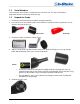
1.0 Introduction 1.1 System Description The RDO® Pro Probe is a rugged, reliable instrument designed to deliver accurate dissolved oxygen (DO) data across a wide measurement range and to reduce maintenance costs. The probe features the latest optical technology for DO measurement.
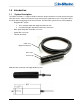
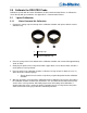
1.2 Serial Numbers The instrument serial number is engraved on the side of the unit. The cap serial number is programmed on the memory chip inside the cap. 1.3 Unpack the Probe 1. Remove the probe from the box and other packaging materials. 2. Unscrew the nose cone from the probe and remove the red protective dust cap from the sensor. Save the dust cap for later use. Nose cone Dust cap 3. Remove the RDO cap from the storage sleeve. 4.
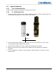
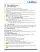
2.0 Calibrate the RDO PRO Probe Calibrate the probe with the Comm Kit Software and the Communication Device, or calibrate the sensor directly with your controller. See Appendix A – Communication Device. 2.1 2.1.1 1-point Calibration Water-Saturated Air Calibration 1. Remove the storage cap from the top of the calibration chamber and replace with the vented calibration cap. 1 Storage cap 2 Vented calibration cap 2.
2.2 2.2.1 2-point Calibration 100% Calibration Point Perform a water-saturated-air calibration as previously described. 2.2.2 0% Calibration Point 1. Remove the water-saturated sponge from the calibration chamber and fill the chamber to the fill line with approximately 60 mL of fresh sodium sulfite solution. 1 Fill line 2 Temperature sensor 2. Place the probe into the solution. Leave at least 13 mm (0.5 in.) between the surface of the sensing element and the bottom of the chamber. 3.
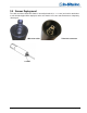
3.0 Sensor Deployment The cable end of the RDO PRO Probe is internally threaded (1¼ – 11½ NPT) and can be attached to a male threaded pipe. When deployed, make sure that the nose cone and thermistor are completely submerged.
4.0 Care and Maintenance 4.1 Clean the RDO Cap 1. The cap and nose cone must remain on the probe. 2. Rinse the sensor with clean water from a squirt bottle or spray bottle. 3. Gently wipe with a soft-bristled brush or soft cloth if biofouling is present. Use Alconox® to remove grease. 4. If extensive fouling or mineral build-up is present, soak the cap end in vinegar for 15 minutes, then soak in deionized (DI) water for 15 minutes. Do not use organic solvents—they will damage the sensing element.
7. Clean the sensor lens with the wipe provided in the kit and allow it to thoroughly dry. Inspect for scratches or dirt. 8. Remove the new cap from its sealed packaging and attach it to the sensor, being careful to press firmly, without twisting, until it seals over the lens. Make sure that the O-rings are not pinched or rolled between the cap and sensor. Replace the nose cone. 9. Perform a 1- or 2-point calibration. 4.
5.0 Controller Requirements and Connections The RDO PRO Probe may be connected to a controller or logger for communication via: • • • • Analog (4-20 mA) provides a configurable 4-20 mA current loop output SDI-12 RS485 Modbus RS232 Modbus 5.1 Wiring Overview Refer to diagrams on the following pages. Trim and insulate unused wires. The shielded wire should be wired to a chassis ground or earth ground.
5.2 Analog (4-20 mA) 3-wire Signal Color Ground/Return Black External Power (12-36 VDC) Red 4-20 mA Brown Cable length must not exceed 1219 m (4000 ft.) Analog signal must be enabled in Win-Situ® 5 Software or the Comm Kit Software prior to use.
5.3 SDI-12 (3 wire) Signal Color Ground/Return Black External Power (9.6-16 VDC) Red RS485 (-) Green RS485 (+) Blue SDI-12 White Cable length must not exceed 60.96 m (200 ft.
5.4 Modbus Master with Built-in RS485 Signal Color Ground/Return Black External Power (12-36 VDC) Red RS485 (-) Green RS485 (+) Blue Cable length must not exceed 1219 m (4000 ft.
5.5 Modbus Master with Built-in RS232 (Converter Required) Signal Color Ground/Return Black External Power Red (12 VDC, voltage limited by converter) RS485 (-) Green RS485 (+) Blue Cable between converter and master must not exceed 60.96 m (20 ft.) Cable between master and slave must not exceed 1219 m (4000 ft.) 5.5.
5.5.2 Power Connections The red wire provides power for all system modes. Analog output is disabled by default. However, the 4-20 mA current loop output can be continuous in Modbus or SDI-12 mode as long as Modbus device register 9507 is set to 1. 5.5.3 Communications The device automatically switches between Modbus and SDI-12 modes depending on which of the two interfaces has activity.
0049 1 R1/W2 ushort Units Id 1 = °C (default) 2 = °F 0050 1 R1 ushort Data Quality Id 0051 2 R1/W3 0053 1 R1 float Off line sentinel value (default = 0.0) 16 bits Available Units = 0x0003 (3) Dissolved Oxygen %Saturation 0054 2 R1 float Measured value 0056 1 R1/W2 ushort Parameter Id = 21 0057 1 R1/W2 ushort Units Id 177 = percent saturation (default) 0058 1 R1 0059 2 R1/W3 0061 1 R1 ushort Data Quality Id float Off line sentinel value (default = 0.
6.3.1 Dissolved Oxygen Concentration Equations DO concentration is internally calculated in mg/L. Conversion to other units is as follows: µg/L = 1000 * mg/L Oxygen concentration Co (mg/L) is calculated as: Co = 31.9988 × 1E6 × (ρPo/koM) (1 − Θo) × Sc Where: Po is the partial pressure of O2 in atmospheres. Ptorr = 759.999876 × Patm Sc is the salinity correction: ln Sc = S(B0 + B1Ts + B2Ts2 + B3Ts3) + C0S2 B0 = -6.246090 × 10⁻³ B1 = -7.423444 × 10⁻³ B2 = -1.048635 × 10⁻² B3 = -7.987907 × 10⁻³ C0 = -4.
6.3.2 Dissolved Oxygen, % Saturation Equations O2%Sat = O2Reading/ O2100%Sat Where: O2 reading is the mg/L reading from the RDO Sensor. O2 100% Sat is the theoretical saturation value in mg/L and is derived as: O2100%Sat = 31.9988 × 10⁶ × ρ [0.20946 × (P – Pwv)] × (1 − ΘoP) × Sc koM Where: ρ is the density of water in g/cm3: ln ρ = -0.589581 + (326.785/T) − (45,284.1/T2) T is the temperature in Kelvin. P is the atmospheric pressure in atm.
6.4 Register Calibration Registers Size Mode & Access Level Data (registers) (R/W) Type Description 0118 2 R1/W3 float Live salinity value (PSU) 0120 2 R1/W3 float Default salinity value (PSU, default = 0.0) 0122 2 R1/W3 float Live barometric pressure (mbar) 0124 2 R1/W3 float Default barometric pressure (mbar, default = 1013.
0% Saturation Calibration Values These values represent the sensor conditions while the probe is in a 0% saturation calibration environment. These are not measured values, they are written by the controller during the calibration process. Writes to these registers are only accepted if the probe is in the calibration mode. The probe will return exception 0x85 (invalid device command sequence) if an attempt is made to write these registers when the calibration mode is off.
12. Write the Calibration Mode Off command (0xE002) to the sensor command register to place the sensor in normal operation. If the calibration mode is turned off without a calibration update command, or the calibration command returned an exception, the previous calibration shall be restored. 13. Optional: If you saved the temperature and saturation parameter units at the start of the process, write the original values back. 14.
7.0 Specifications Optical RDO PRO Dissolved Oxygen Probe Sensor type Optical (luminescent) dissolved oxygen sensor Range: 0 to 50 mg/L concentration; 0 to 200% saturation RDO PRO Probe Accuracy: ±0.1 mg/L, 0 to 8 mg/L ±0.2 mg/L, 8 to 20 mg/L ±10% of reading, 20 to 50 mg/L Resolution: 0.
8.0 Accessories and Replacement Parts Accessory Order No. RDO PRO Sensor Cap Replacement Kit................................................................................ 0084230 RDO PRO Calibration Kit ....................................................................................................... 0088890 Manual, RDO PRO Probe ...................................................................................................... 0089662 RDO PRO Communication Device Kit……………..……………………………………………....
10.0 Appendix A – Communication Device The Communication Device is an accessory product that can be used to calibrate and set up RDO probes. 10.1 Install and Open the Software The Comm Kit Software must be installed on a computer before you connect to the probe. 10.2 Connect the Probe to the Communication Device The Communication Device connects a stripped-and-tinned probe to a computer via USB connection. 1. Disconnect the instrument from the PLC. 2.
11.0 Declaration of Conformity Manufacturer: In-Situ, Inc. 221 East Lincoln Avenue Fort Collins, CO 80524 USA Declares that the following product: Product name: Model: Product Description: RDO PRO Optical Dissolved Oxygen Sensor RDO PRO Optical Dissolved Oxygen Sensor The RDO PRO measures dissolved oxygen and temperature in natural groundwater and surface water.