
Reference Guide User Manual
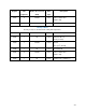
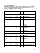
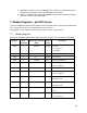

Register Size
(registers)
Mode & Access Level
(R/W)
Data
Type
Description
1014 3 R1/W2 time Next user calibration
(0 = none required)
1017 1 R1 ushort Warm-up time in milliseconds = 800
1018 1 R1 ushort Fast sample rate = 800 milliseconds
1019 1 R1 ushort Number of sensor parameters (N) = 3
1020 1 R1/W3 ushort Alarm/warning parameter number
(1 – N, default = 1)
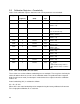
1021 1 R1/W3 16 bits Alarm and warning enable bits
(default = 0)
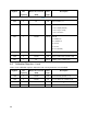
Bit 0
= High alarm enabled
Bit 1
= High warning enabled
Bit 2
= Low warning enabled
Bit 3
= Low alarm enabled
Bit 4
= Sensor calibration warning
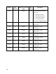
1022 2 R1/W3 float High alarm set value (default = 0.0)
1024 2 R1/W3 float High alarm clear value (default = 0.0)
1026 2 R1/W3 float High warning set value (default = 0.0)
1028 2 R1/W3 float High warning clear value
(default = 0.0)
1030 2 R1/W3 float Low warning clear value
(default = 0.0)
1032 2 R1/W3 float Low warning set value (default = 0.0)
1034 2 R1/W3 float Low alarm clear value (default = 0.0)
1036 2 R1/W3 float Low alarm set value (default = 0.0)
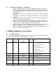
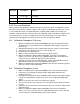
6.1.1 Warm-up Time
If automatic density correction is disabled, this register returns the level sensor warm-up time as
shown. If automatic density correction is enabled, this register returns the sum of the level
sensor and conductivity sensor warm-up times.
44