
Reference Guide User Manual
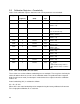

5.4 Calibration Procedure—Conductivity
1. Write the Calibration Mode On command (0xE000) to the Sensor Command
register. Reading the actual conductivity parameter in calibration mode shall
present actual conductivity as AC
f
(the current cell offset and cell constant shall
not be applied).
2. Instruct the user to place the conductivity sensor into one or more conductivity
standards.
3. Read the actual conductivity and temperature parameters at each conductivity
standard.
4. Calculate new values for the cell offset K
0
and cell constant K and write these
values to their corresponding registers.
5. Write the Calibration Update command (0xE001) to the Sensor Command
register. The sensor sets the Last User Calibration Date to the current date and
sets the Next User Calibration Date to zero (none required).
6. Optionally, read the Last User Calibration Time register, add the next calibration
interval, and write the result to the Next User Calibration Time register.
7. Write the Calibration Off command (0xE002) to the sensor command register to
place the sensor in normal operation.
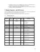
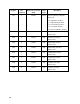
6. Modbus Registers—Level Sensor
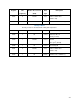
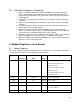
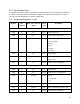
6.1 Header Registers
The sensor map data register offset points to the first register in the sensor data header block.
The current value for this sensor data register map version is 1.
Register Size
(registers)
Mode & Access Level
(R/W)
Data
Type
Description
1001 1 R1/W4 ushort Sensor ID
34 = 30 foot full-scale level,
absolute pressure
32 = 100 foot full-scale level,
absolute pressure
33 = 250 foot full-scale level,
absolute pressure
1002 2 R1/W4 ulong Sensor serial number
1004 1 R1 16 bits Sensor status
1005 3 R1/W4 time Last factory calibration
1008 3 R1/W4 time Next factory calibration
(0 = none required)
1011 3 R1 time Last user calibration
43