Aqua TROLL 400 Multiparameter Instrument Modbus and SDI-12 Reference Guide March 2014 rev.
Table of Contents 1. 2. 3. 4. 2 Controller Requirements and Connections .......................................................................... 6 1.1 Wiring Overview.................................................................................................... 6 1.2 Power Connections ............................................................................................... 6 1.3 SDI-12 Wiring Diagram .....................................................................................
4.12 Live Barometric Pressure .....................................................................................33 4.13 Default Barometric Pressure ................................................................................33 4.14 100% Saturation Calibration Values .....................................................................33 4.15 Zero% Saturation Calibration Values ...................................................................33 4.16 Calibration Slope and Offset ............
8. Appendix—Modbus Additional Information.........................................................................55 8.1 Modbus Tutorial ...................................................................................................55 8.2 Modbus Modes ....................................................................................................55 8.3 Protocol Overview ................................................................................................56 8.
8.15 Probe Common Registers ....................................................................................69 8.16 Communication Control Registers........................................................................70 8.17 Sensor Connection Registers ..............................................................................70 8.18 Current Loop Configuration Registers ..................................................................71 8.19 Logged Record Registers .......................
1. Controller Requirements and Connections The Multi-PRO 400 may be connected to a controller or logger for communication via: 1.1 • SDI-12 • RS485 Modbus • RS232 Modbus (with converter) Wiring Overview Refer to the diagrams on the following pages. Trim and insulate unused wires. The shielded wire should be wired to a chassis ground or earth ground. Cable Stripped and Tinned Signal Ground/Return External Power No Connection RS485 (-) RS485 (+) SDI-12 1.
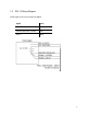
1.3 SDI-12 Wiring Diagram Cable length must not exceed 60.9 m (200 ft). Signal Color Ground/Return Black External Power (9.
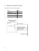
1.4 Modbus Master RS485 Wiring Diagram Cable length must not exceed 1219.2 m (4000 ft).
1.5 Modbus Master RS232 Wiring Diagram (Converter Required) Cable length between Master and Slave must not exceed 1219.2 m (4000 ft). Rugged Cable length between Master and Converter must not exceed 6 m (20 ft).
1.6 RS485 Network Guidelines The manufacturer uses RS485 as its main digital communications link. RS485 is often used in an industrial setting as a small device network. There are some installation guidelines to follow when configuring an RS485 network with implications to use with the instrument. RS485 Rule 1 RS485 is a bus network. It does not work when configured in a star network topology.
DB-9 Pin Diagram Pin Signal Name 1 Carrier Detector DCD 2 Receive Data RXD 3 Transmit Data TXD 4 Data Terminal Ready DTR 5 Signal Ground/Common GND 6 Data Set Ready DSR 7 Request to Send RTS 8 Clear to Send CTS 9 Ring Indicator RI 11
2. SDI-12 Interface The Multi-PRO 400 Instrument adheres to the Serial Digital Interface Standard for Microprocessor-based sensors, version 1.3, and the extensions to the specifications identified in this document. This section identifies the device-specific implementation of the standard. For more information on SDI-12 see www.sdi-12.org. 2.
2.2 Device Identification In response to the Send Identification command, the instruments respond as follows: 1. Device address 2. SDI-12 compatibility (Version 1.3) 3. Manufacturer 4. Instrument model 5. Firmware version (100 = 1.00) 6.
2.3 Basic Commands The following table lists each basic SDI-12 command, its format, and the format of each response. Name Command Response Address Query ?! a The wildcard address ‘?’ character is supported only for the Address Query command. It is ignored as an invalid address for all other commands. Acknowledge Active a! a Basic address characters in the range ‘0’ to ‘9’ and the extended address characters in the ranges ‘A’ to ‘Z’ and ‘a’ to ‘z’ are supported.
Name Command Start Measurement aM! Start Measurement CRC aMC! Response a004n n parameters will be available for reading by the Send Data command within 4 seconds. A service request (a) will be sent when the parameters are ready. The number of parameters returned is determined by the SDI-12 configuration file. The default value for n is 7.
Name Command Response Start Concurrent aC! a004nn Start Concurrent CRC aCC! nn parameters will be available for reading by the Send Data command within 4 seconds. No service request will be sent when the parameters are ready. The number of parameters returned is determined by the SDI-12 configuration file in the same manner as a Start Measurement command.
2.4 Extended Commands The Multi-PRO 400 Instrument supports the following extended SDI-12 commands. Name Set Factory Defaults Send Data Set Output Sequence Command Response aXFD! a0011 One result is available in 1 second for reading by the Send Data command. Restores all settings and calibration values to their factory defaults. aD0! a+s s = command status, 1 = command successful, 0 = command failed.
Name Set Temperature Units Command aXTUnnn! Response aOK or aERROR nnn = the temperature units ID Three digits are required. Read Temperature Units aXTU! annn nnn = temperature units ID Restore DO Factory Calibration aXoFC! a0011 One result is available in 1 second for reading by the Send Data command. Restores DO sensor slope and offset calibration values to their factory defaults. No change to other parameter settings.
Name Set Specific Conductivity Alpha Command aXCApd.d! Response aOK or aERROR pd.d = alpha p = polarity sign (+ or -) d = digits (1 to 7) . = decimal point (optional) Read Specific Conductivity Alpha aXCA! apd.d pd.d = Alpha Set Specific Conductivity Reference Temperature aXCTpd.d! aOK or aERROR pd.d = reference temperature p = polarity sign (+ or -) d = digits (1 to 7) . = decimal point (optional) Read Specific Conductivity Reference Temperature aXCT! apd.
Name Set Conductivity Cell Constant Command aXCKpd.d! Response aOK or aERROR pd.d = cell constant p = polarity sign (+ or -) d = digits (1 to 7) . = decimal point (optional) Read Conductivity Cell Constant aXCK! apd.d pd.d = cell constant Set Pressure Units aXPUnnn! aOK or aERROR nnn = the pressure units ID Three digits are required.
Name Command Response aXLFC! a0011 One result is available in 1 second for reading by the Send Data command. Restores pressure and level calibrations to their factory defaults. No change to other parameter settings. aD0! a+s s = command status, 1 = command successful, 0 = command failed. Zero Pressure aXPZ! a0011 One result is available in 1 second for reading by the Send Data command. A service request (a) will be sent when the result is ready.
Name Set pH Slope Command aXHSpd.d! Response a0011 One result is available in 1 second for reading by the Send Data command. A service request (a) will be sent when the result is ready. pd.d = pH slope (pH/mV at 25 °C, must be less than zero) p = polarity sign (+ or -) d = digits (1 to 7) . = decimal point (optional) aD0! a+s s = command status, 1 = command successful, 0 = command failed (sensor not plugged in).
Name Set ORP Offset Command aXrOpd.d! Response a0011 One result is available in 1 second for reading by the Send Data command. A service request (a) will be sent when the result is ready. pd.d = ORP offset (+/- 1000 mV) p = polarity sign (+ or -) d = digits (1 to 7) .
Name ISCO Compatibility Command aXPR0! Response aIxIxIxIx Each Ix is a character pair identifying the parameter and units for each measurement. The number of Ix pairs equals the number of data values returned for the Start Measurement and Start Concurrent commands.
2.5 SDI-12 Configuration File The SDI-12 configuration file can be edited using the Comm Kit Software and the Communication Device. 2.5.1 Connect the Communication Device and Comm Kit Software The Communication Device connects a stripped-and-tinned cable and instrument to a computer via USB connection and enables a connection with the Comm Kit Software. 1. The communication device includes an electrical connection diagram label.
2.5.2 SDI-12 Setup SDI-12 setup allows you to set the instrument address, select the parameters you intend to log, and select the order in which the parameters will appear in the log. Screen Element Purpose Address character Allows you to assign a unique SDI-12 address to the instrument. Use 0-9, A-Z, or a-z. (text field) Reload From Device Restores the settings that were last written to the instrument. (button) Write to Device Writes the parameters and the address to the instrument.
3. Modbus Registers—Probe 3.1 Modbus Communication Setup See Connect the Communication Device on page 25. Click the Modbus setup button and assign instrument settings according to the requirements of the controller. The following Modbus registers are specific to the instrument. More information about Modbus, including protocol specifications can be downloaded from www.modbus.org.
3.3 Automatic Barometric Correction Set this register to 0 to disable automatic barometric correction. Set to 1 to enable automatic barometric correction. The default is disabled. If enabled, the level sensor shall subtract the live barometric pressure register from its pressure sensor readings. This register shall not affect how the RDO sensor utilizes the live barometric pressure register to calculate its parameters. 3.
Register 0020 Size Mode & Access Level Data Description (registers) (R/W) Type 1 R1/W3 ushort Alarm/warning parameter number (1 – N, default = 1) 0021 1 R1/W3 16 bits Alarm and warning enable bits (default = 0) Bit 0 = High alarm enabled Bit 1 = High warning enabled Bit 2 = Low warning enabled Bit 3 = Low alarm enabled Bit 4 = Sensor calibration warning 0022 2 R1/W3 float High alarm set value (default = 0.0) 0024 2 R1/W3 float High alarm clear value (default = 0.
4.5 Next Factory Calibration This field returns the expiration time of the installed sensor cap. This value is the lesser of the cap manufactured time plus 24 months, or the cap start time plus 12 months. The probe returns zero if the sensor cap is not installed. 4.6 Warm-Up Time If automatic salinity correction is disabled, this register returns the RDO sensor warm-up time.
Register Size Mode & Access Level Data Description (registers) (R/W) Type 0048 1 R1 ushort Parameter ID = 1 0049 1 R1/W2 ushort Units ID 1 = °C (default) 2 = °F 0050 1 R1 ushort 0051 2 R1/W3 float 0053 1 R1 16 bits Data Quality ID Off line sentinel value (default = 0.0) Available Units = 0x0003 (3) Dissolved Oxygen %Saturation The saturation parameter is calculated from dissolved oxygen concentration and settings contained in the sensor calibration registers.
Register 4.9 Size Mode & Access Level Data (registers) (R/W) Type 0066 1 R1 ushort 0067 2 R1/W3 float 0069 1 R1 16 bits Description Data Quality ID Off line sentinel value (default = 0.0) Available Units = 0x0200 (512) Calibration Registers—RDO Values in the calibration registers determine how the sensor parameters are calculated.
4.10 Live Salinity Value The live salinity value is used to correct the oxygen concentration value for salinity when automatic salinity correction is disabled. Values must be written in Practical Salinity Units (PSU) in the range 0 to 42 PSU. This is not a measured parameter. If automatic salinity correction is enabled, the salinity value is obtained from the conductivity sensor and the live salinity will have no effect. 4.
4.16 Calibration Slope and Offset These values represent the slope and offset that will be applied to the raw concentration reading from the sensor to generate the final values reported by the sensor parameters. Writes to these registers are only accepted if the probe is in the calibration mode. The probe will return exception 0x92 (invalid sensor) if an attempt is made to write these registers when the calibration mode is off.
4.17.1 RDO Calibration Calculations Calibrated Oxygen reading: O2 RC = c0 + c1 × O2 RU where: c1 = O2100% Sat O2 RUS − O2 RUZ c0 = −c1 × O2 RUZ where: O2100% Sat is the theoretical 100% saturation point. O2 RUS is the un-calibrated reading at 100% saturation. O2 RUZ is the un-calibrated reading at 0% saturation. References: Standard Methods: 4500-0 C.
5. Modbus Registers—Conductivity Sensor 5.1 Header Registers—Conductivity The sensor map data register offset points to the first register in the sensor data header block. The current value for this sensor data register map version is 1.
Register 0524 Size Mode & Access Level Data (registers) (R/W) Type 2 R1/W3 float Description High alarm clear value (default = 0.0) 0526 2 R1/W3 float High warning set value (default = 0.0) 0528 2 R1/W3 float High warning clear value (default = 0.0) 0530 2 R1/W3 float Low warning clear value (default = 0.0) 0532 2 R1/W3 float Low warning set value (default = 0.0) 0534 2 R1/W3 float Low alarm clear value (default = 0.
5.2 Parameter Registers—Conductivity Register Size Mode & Access Level Data (registers) (R/W) Type Description Actual Conductivity 0538 2 R1 float 0540 1 R1 ushort Measured value, AC Parameter ID = 9 (actual conductivity) 0541 1 R1/W2 ushort Units ID 65 = microsiemens per centimeter (default) 66 = millisiemens per centimeter 0542 1 R1 ushort 0543 2 R1/W3 float Data Quality ID Off line sentinel value (default = 0.
Register Size Mode & Access Level Data (registers) (R/W) Type Description Specific Conductivity The default units for specific conductivity are uS/cm. Conversion to other units is as follows. mS/cm = uS/cm / 1000 Specific conductivity is calculated from actual conductivity and temperature using the following equation. SC = AC * (β0 + β1T + β2T + … + β 7T ) / (1 + α (T-Tref)) 2 7 Where Tref, α, and β 0-7 are specified in the sensor calibration registers.
Register 0567 Size Mode & Access Level Data (registers) (R/W) Type 2 R1/W3 float Description Off line sentinel value (default = 0.0) 0569 1 R1 16 bits Available Units = 0x0001 (1) Total Dissolved Solids The default units for TDS are ppt. Conversion to other units is as follows. ppm = ppt * 1000 TDS is calculated from specific conductivity using the following equation. TDS = CFTDS * SC Where CFTDS is the TDS conversion factor in ppm units as specified in the sensor calibration registers.
Register 0583 Size Mode & Access Level Data (registers) (R/W) Type 2 R1/W3 float Description Off line sentinel value (default = 0.0) 0585 1 R1 16 bits Available Units = 0x0001 (1) Density of Water Density of water is calculated from salinity and temperature.
5.3 Calibration Registers—Conductivity Values in the calibration registers determine how sensor parameters are calculated. Register Size Mode & Access Level Data Description (registers) (R/W) Type 0628 2 R1/W3 float Cell Offset, K0 (default = 0.0) 0630 2 R1/W3 float Cell Constant, K (default = 1.
5.4 Calibration Procedure—Conductivity 1. Write the Calibration Mode On command (0xE000) to the Sensor Command register. Reading the actual conductivity parameter in calibration mode shall present actual conductivity as ACf (the current cell offset and cell constant shall not be applied). 2. Instruct the user to place the conductivity sensor into one or more conductivity standards. 3. Read the actual conductivity and temperature parameters at each conductivity standard. 4.
Register 1014 Size Mode & Access Level Data (registers) (R/W) Type 3 R1/W2 time Description Next user calibration (0 = none required) 1017 1 R1 ushort Warm-up time in milliseconds = 800 1018 1 R1 ushort Fast sample rate = 800 milliseconds 1019 1 R1 ushort Number of sensor parameters (N) = 3 1020 1 R1/W3 ushort Alarm/warning parameter number (1 – N, default = 1) 1021 1 R1/W3 16 bits Alarm and warning enable bits (default = 0) Bit 0 = High alarm enabled Bit 1 = High warnin
6.1.2 Fast Sample Rate If automatic density correction is disabled, this register returns the level sensor fast sample rate as shown. If automatic density correction is enabled, this register shall return the sum of the level sensor and conductivity sensor fast sample rates. 6.
Register Size Mode & Access Level Data (registers) (R/W) Type Description Level 1054 2 R1 float 1056 1 R1/W2 ushort Measured value, Lm Parameter ID 3 = level, depth (default) 4 = level, top of casing 5 = level, elevation 1057 1 R1/W2 ushort Units ID 33 = millimeters 34 = centimeters 35 = meters 37 = inches 38 = feet (default) 6.3 1058 1 R1 ushort 1059 2 R1/W3 float 1061 1 R1 16 bits Data Quality ID Off line sentinel value (default = 0.
6.3.1 Pressure Calculation If automatic barometric pressure correction is disabled, the raw pressure reading (P) is simply the pressure reading of the sensor (PS). P = PS If automatic barometric pressure correction is enabled, the live barometric pressure value (PB, see RDO sensor) is subtracted from the pressure sensor reading (PS) to generate the raw pressure reading. P = PS - PB 6.3.
Parameter Description Equation 3 Level, depth LM = D(PM) 4 Level, top of casing 5 Level, elevation LM = LR – (D(PM)– DR) LM = LR + (D(PM) – DR) 6.3.5 Pressure Reference Master software may optionally overwrite the pressure reference value recorded by the device when the Level Reference register is written. This register can be written only when the sensor is in the calibration mode.
8. Optionally, read the Last User Calibration Time, add the next calibration interval, and write the result to the Next User Calibration Time register. 9. Write the Calibration Off command (0xE002) to the Sensor Command register to place the sensor in normal operation. 7. Modbus Registers – pH/ORP Sensor The Sensor Map Data Register Offset points to the first register in the sensor data header block. The current value for this sensor data register map version is 1.
Register 1521 Size Mode & Access Level Data (registers) (R/W) Type 1 R1/W3 16 bits Description Alarm and warning enable bits (default = 0) Bit 0 = High alarm enabled Bit 1 = High warning enabled Bit 2 = Low warning enabled Bit 3 = Low alarm enabled Bit 4 = Sensor calibration warning 1522 2 R1/W3 float High alarm set value (default = 0.0) 1524 2 R1/W3 float High alarm clear value (default = 0.0) 1526 2 R1/W3 float High warning set value (default = 0.
7.2 Parameter Registers Register Size Mode & Access Level Data (registers) (R/W) Type Description pH If the parameter value is read when the sensor is not plugged in, it returns the sentinel value and a Data Quality ID of 7 (sensor communication error). If the parameter value calculates to a value outside of the range 0 to 14 pH, it shall return the sentinel value and a Data Quality ID of 3 (error).
Register 4557 Size Mode & Access Level Data (registers) (R/W) Type 1 R1/W2 ushort Description Units ID 162 = mV (default) 7.3 4558 1 R1 ushort 4559 2 R1/W3 float 4561 1 R1 16 bits Data Quality ID Off line sentinel value (default = 0.0) Available Units = 0x0002 (2) Calibration Registers—pH/ORP These registers can be written only when the sensor is in the calibration mode.
Register Size Mode & Access Level Data Description (registers) (R/W) Type 1641 2 R1/W3 float 1643 2 R1/W3 float Offset, b2 in pH (default = 7.0) 1645 1 R1/W3 ushort ORP solution type (default = 0) 1646 2 R1/W3 float mV value of solution (default = 0) 1648 2 R1/W3 float mV response in solution (default = 0) 1650 2 R1/W3 float 1652 2 R1/W3 float 1654 2 R1/W3 float Slope, m2 in pH/mV (default = -0.
7.3.2 ORP Measured Value The measured value is derived as follows: ORP = morp × mV + borp Where: mV is the measured sensor millivolts morp and borp are slope and offset respectively ORP is the calculated value 7.4 Calibration Procedure—pH 1. Write the Calibration Mode On command (0xE000) to the Sensor Command register. 2. Place the pH sensor into one or more pH standards. 3. Read the pH mV and temperature parameters at each pH standard. 4.
8. Appendix—Modbus Additional Information The Multi-PRO 400 Instrument supports Modbus as its primary communication protocol. This appendix contains a brief Modbus tutorial intended to accelerate learning for a person who is not familiar with the protocol. This document is not an official protocol document. More information about Modbus, including protocol specifications, can be downloaded from www.modbus.org.
• • 8.3 ASCII format is required for any kind of wireless serial communications because it eliminates the message timing requirements needed for RTU mode. Message timing can be erratic over a wireless link. IP formatted messages can be used when the messages are transported using a secondary transport protocol such as TCP/IP. In this case the secondary transport protocol ensures that all of the packet bytes are transported correctly.
8.5.2 Device (Slave) Response Format Device Address • • • • 8.6 Function Code Data Payload CRC Device Address: Echo of device address sent in the message to the device. A broadcast message will not generate a response. Function Code: Echo of the function code sent to the device in the message packet. If an error occurs, the top bit of the byte is set and the data payload is the 1 byte error code from the device. Data Payload: 0-N bytes with response data from the device.
• • • • 8.7 Function Code: 2 byte field with a value range 1-127 representing the standard or extended function code in hex characters. Data Payload: 0-N bytes with response data from the device in hex characters. For an error response, the payload will be a 1 byte value 1-255. LRC: 2 bytes represented in hex characters with a value computed mathematically from the message bytes.
device will always have a published “Register Map” that defines the numerical addresses of data values that can be accessed in the device. Note: Register Maps typically use a 1-based numbering system whereas the protocol requires the data address/register number passed to a device to be 0-based. In this document, the register maps are 1-based. Data addresses are associated with two atomic sizes of memory, 1 bit and 2 bytes.
8.10.1 Read Holding Registers This command reads one or more registers from a device. Message (8 bytes): Response (5 + N bytes): Address 1 Byte 1-247 Address 1 Byte 1-247 Function Code 1 Byte 0x03 Function Code 1 Byte 0x03 Data Address 2 Bytes 1 Byte 0 to 0xFA Register Count 2 Bytes CRC 2 Bytes 0 to 0xFFFF Byte Count 0 to 0x7D Data Payload N Bytes CRC 2 Bytes Where Byte Count is the #bytes in the Data Payload (does not include CRC bytes). Byte Count = 2 * Register Count. 8.10.
Where Byte Count is the #bytes in the Data Payload (does not include CRC bytes). Byte Count = 2*Register Count. The register count is limited to a single data format field. If an attempt is made to write a data field with an incorrect register count, the device will return a Modbus exception response with error code 0x80. 8.10.4 Mask Write Register This command will set and/or clear one or more bits in a single register.
8.10.5 Report Slave ID This command query’s a device for ID information. Message (4 bytes): Response (N bytes): Address 1 Byte 1-247 Address 1 Byte 1-247 Function Code 1 Byte 0x11 Function Code 1 Byte 0x11 CRC 2 Bytes Byte Count 1 Byte 0 to 0xFF Slave ID 1 Byte 0 to 0xFF Run Status 1 Byte 0 to 0xFF • • • Data Payload N Bytes CRC 2 Bytes The Data Payload layout is defined in the Slave ID Format section.
Byte Offset Field Description Type 18-21 Device Serial Number ulong 22-23 Max Message/Response Size (bytes) ushort 24-25 Max Baud Rate ID ushort 26-27 CRC Value The specific field values such as device ID, baud ID, etc. are documented in the sections that follow. 8.11 Instrument Manufacturer Data Types Modbus defines all I/O in terms of 2 byte blocks called registers. Modbus does not formally define blocks for floating point values or strings.
8.11.4 Unsigned Long A 4-byte unsigned integer contained in two register data address’s. IEEE standard. MSB 8.11.5 XXXX XXXX XXXX XXXX XXXX XXXX XXXX XXXX Byte 0 Byte 1 Byte 2 Byte 3 LSB Float IEEE 4-byte numeric standard – 1 sign bit, 8-bit exponent, 23-bit mantissa. MSB SXXX XXXX XMMM MMMM MMMM MMMM MMMM MMMM Byte 0 Byte 1 Byte 2 Byte 3 LSB Where S = sign bit, X = exponent bits and M = mantissa bits. 8.11.
8.11.9 Time Time is represented by a 6-byte (3 register) number. The first 4 bytes represent the number of seconds since 00:00:00 January 1, 1970 UTC, MSB first, not adjusted for DST. The 5th and 6th bytes are fractions of a second represented by the bits in powers of 2 starting with the MSB. If a device does not have the ability to support the full fractions of a second resolution available in the time format, unused bits must be set to 0.
8.12 Exception Codes The instrument manufacturer supports the standard Modbus exception codes but also provides additional exception codes to assist with troubleshooting problems. Code 1 Name Illegal Function Description The function code received in the query is not an allowable action for the slave. If a Poll Program Complete command was issued, this code indicates that no program function preceded it.
Code Name Description 0x0A Gateway Path Specialized use in conjunction with gateways, indicates that Unavailable the gateway was unable to allocate an internal communication path from the input port to the output port for processing the request. Usually means that the gateway is misconfigured or overloaded. This exception code may not be supported by the devices.
Code 0x94 Name Sensor Missing Description Attempting a sensor operation on a sensor port with no sensor connected. 0x95 Sensor Invalid Attempting a sensor operation on a sensor port that has a sensor that is not compatible with the sensor that was originally configured. 0x96 Sensor Firmware Attempting a sensor operation on a sensor with no application code. 0xA0 Data Log Register Attempting to write a register that is read-only during logging. 0xA1 Data Log Memory Data log memory is full.
All registers in this document are 1-based. This means the actual packets sent to the devices must have a data address 1 less than what the register number is in this document. 8.
8.
Register Size Mode Data Description XXXX (registers (R/W) Type 9311 1 R1 ushort Connection 2 sensor data register map version 9312 1 R1 ushort Connection 2 sensor data register offset Level Sensor 9313 1 R1 ushort Connection 3 sensor id 9314 1 R1 ushort Connection 3 sensor status 9315 1 R1 ushort Connection 3 sensor command 9316 1 R1 ushort Connection 3 sensor data register map version 9317 1 R1 ushort Connection 3 sensor data register offset pH/ORP Sensor 9318 1 R1 u
8.19 Logged Record Registers Register Size Mode Data Description XXXX (registers (R/W) Type 9600-601 2 R1 9602-603 2 R1/W3 9604-606 3 R1 time Time stamp for record 9607-608 2 R1 float Parameter 1 measured value 9609 1 R1 96010-696 29 x 3 R1 ulong Number of logged records ulong Requested log record number ushort Parameter 1 data quality ID --- Parameters 2 – 30 (30 is max allowed #log parameters) 8.
8.21 Device ID Device ID for Multi-PRO 400 = 18 8.22 Device Serial Number This is a 6-digit serial number engraved on the device. Serial numbers for devices in this system will range from 000001 to 999999. 8.23 Manufacture Date This is the date and time of manufacture in the Time format. 8.24 Firmware, Boot Code, Hardware Versions The firmware and boot code versions will be the floating point version multiplied by 100 to create an integer. For example, version 1.32 will be stored as 132.
8.29 Device Status The device status register holds general status information. Each set bit represents a status value. There are a limited number of standardized predefined status values that all devices will support. These predefined status values are contained in the lower register. The upper register is reserved for device specific status values.
8.30 Serial Communication Configuration The 16 bits in this register are mapped to the communication parameters.
8.31 Baud Rates The instrument supports 9600 through 57600 baud rates. A device will support all baud rates from 9600 up to and including the maximum baud rate as specified by the Max Baud Rate ID register. • If the Master attempts to set the baud rate of a device to a non-supported value, the device will respond with a Modbus exception error code 3 (Illegal Data Value). • Baud rates will be referenced in this document by the ID 0-7. 8.
• • Bad Message Counter – count of number of improperly formatted messages received (i.e. bad CRC). Bad messages might not be associated with this device because it is impossible to determine if a bad message was addressed to the device or not. Exception Response Counter – count of the number of messages received that were rejected with a Modbus exception response. 8.36 Sensor Connection Registers 8.36.
8.37 Sensor Map Registers 8.37.1 Sensor ID Registers These registers duplicate the Sensor ID register provided in each sensor’s Sensor Data Header Register block. If a sensor connection is open, the probe returns a zero. If an attempt is made to access a Sensor ID register that is not mapped to a sensor (one that exceeds the maximum number of sensors supported by the probe), the probe will return an exception response with error code 0x02 (illegal data address). 8.37.
8.37.5 Sensor Data Register Map Offsets These registers specify the register number of the first register in each sensor’s Sensor Data Header Block. These registers assume the 4x (holding register) reference ID and therefore will not contain the reference ID as part of the value (i.e. 40001 will be stored as 1).