HMI Series Panel PC Intel Atom Z Series 3.5” SBC, Low Power, High Performance Design with Intel Atom Z Series Platform, TFT LCD and 10/100/1000 base-T Ethernet. User Guide Version 1.
FCC Statement This device complies with part 15 FCC rules. Operation is subject to the following two conditions: This device may not cause harmful interference. This device must accept any interference received including interference that may cause undesired operation. This equipment has been tested and found to comply with the limits for a class "a" digital device, pursuant to part 15 of the FCC rules.
Copyright Notice ALL RIGHTS RESERVED. No part of this document may be reproduced, copied, translated, or transmitted in any form or by any means, electronic or mechanical, for any purpose, without the prior written permission of the original manufacturer. Trademark Acknowledgement Brand and product names are trademarks or registered trademarks of their respective owners.
Check List Before using this BOX PC, please make sure that all the items listed below are present in your package 1 x HMI Series PPC unit 1 x Driver Utility CD 1 x HMI User Guide 1 x I931 User Manual Make sure that all of the items listed above are present. Do not attempt to apply power to the system if there is damage to any of its components.
Safety Precautions Warning! Always completely disconnect the power cord from your chassis whenever you work with the hardware. Do not make connections while the power is on. Sensitive electronic components can be damaged by sudden power surges. Only experienced electronics personnel should open the PC chassis. Caution! Always ground yourself to remove any static charge before touching the CPU card. Modern electronic devices are very sensitive to static electric charges.
Safety and Warranty 1. 2. 3. Please read these safety instructions carefully. Please keep this user's manual for later reference. Please disconnect this equipment from any AC outlet before cleaning. Do not use liquid or spray detergents for cleaning. Use a damp cloth. 4. For pluggable equipment, the power outlet must be installed near the equipment and must be easily accessible. 5. Keep this equipment away from humidity. 6. Put this equipment on a reliable surface during installation.
Revision History Version Date Note 0.8 2010/9/8 First Version Cage Hsu 1.
Contents Chapter 1 GENERAL INFORMATION....................................................................... 9 1-1 Introduction ............................................................................................. 9 1-2 I931 SBC and Atom Z5xx series Panel PC System Specifications .... 10 1-3 LCD Selection Guide ............................................................................. 11 1-4 HMI Series Brief ....................................................................................
Chapter 1 GENERAL INFORMATION 1-1 Introduction The Z5xx series Panel PC is high performance, low power PC with Intel® US15W XL Chipset combine with a TFT LCD Panel. The Intel Core Duo high performance Processor delivers the most performance per watt available in the market. The Panel PC is designed to satisfy most of the applications in the industrial market, such as POS, KIOSK, Industrial Automation, HMI and Programmable Control System.
1-2 I931 SBC and Atom Z5xx series Panel PC System Specifications CPU Type CPU Speed CPU FSB Chipset BIOS VGA LVDS Intel Atom Z series Processor 1.1GHz/1.6GHz 533MHz Intel US15W AMI 4M Flash Intel® GMA500 Integrated Graphics Engine Intel® GMA500 Integrated Graphics Engine built-in, 24 bits single-channel panel support up to UXGA panel resolution.
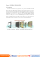
1-3 LCD Selection Guide The HMI series Panel PCs support form 5.7-inch, 7-inch, 10.1-iinch TFT Panel w/ touchscreen function, please refer the below: Size 5.7” 7” 10.1” Model Name Resolution R05I93S-IPD1HM 640 x 480 W05I93S-IPA2HM 800 x 480 W10I93S-IP11HM 1024 x 600 Display Color 262k 262k 256k 1-4 HMI Series Brief Size Model Name 5.7” R05I93S-IPD1HM 7” W05I93S-IPA2HM 10.1” W10I93S-IP11HM IO 1 x Terminal Block(Phoenix Type) 1 x RS232 1 x RS232/422/485(Optional) 2 x USB 2.
Chapter 2 Getting Started 2-1 Input / Output Devices The following figure shows the I/O arrangement of the Panel PC. The backside of the chassis contains most of the connectors (7” for example). 1 2 3 4 5 6 7 RJ-45 VGA CAN BUS (Optional) USB RS-232 DC-in RS-232/422/485 2 x RJ45-10/100/1000 1 x VGA (D Sub 15p Female) 1 x 2channel CAN BUS (ch1, ch2 ) 2 x USB 2.
2-2 Starting the Panel PC& O/S Installation 1. Connect the power to 12V DC power supply to 3 pins Terminal block (Phoenix Type) Terminal Block Male Part Terminal Block Female Part Connect to Terminal block on PPC (a) Please use external USB DVD-ROM to run the O/S and Driver setting (as 2. 3. 4. Press the power on switch to start the Panel PC. Press “DEL” to enter the CMOS setting and check the BIOS setup. You may install your own O/S if it is not installed.
2-3 Driver Installation The PPC comes with a I931 User’s Manual and Driver CD that contains most of the drivers and utilities of your needs. a) Following the step by step to install Driver (Please refer I931 SBC User’s Manual Chapter 3, 4, 5, 6) include: Chipset, VGA, Audio, and Ethernet b) Following the step by step to install the Touch screen if necessary (Please refer S series PPC User Guide Chapter 3).
Chapter 3 Driver Installation 3-1 Touch Driver Installation HMI series default is Premier Touch. The touchscreen system consists of a touchscreen and an electronic touchscreen controller. The attached Driver CD contains drivers of the touch panel controller. Follow the steps as below to install TouchKit: Step1 Put the TouchKit CD to CD-ROM Step2 Open the Win2000_XP directory. Step3 Double click the Setup.exe, then system starts to run the installation program.
Step.2 Enter “General” function and choose the language you need. Step.3 Correct 4 point locations on screen with the Panel.
Step.4 Play “Yes” to continue if 4 points calibration test is fine and finish the test 3-2 CAN BUS Driver Installation HMI Series support 2 channels CAN BUS. H1 L1 H2 L2 Step1. Enter CAN BUS floder. Install “dotnetfx2.0.exe” first.
Step2. Enter CAN BUS Folder. Install “setup.msi”. Then finish the installation. 3-3 Brightness Adjustment In our new product – 10.1” Panel PC, the dimming control has to install drivers and software to work brightness control properly. Please do following steps: Step1 Installing Driver You can find the driver in the Touch & Driver CD. Find the 「Backlight Control Driver」 folder and double click the “install.bat” install file. Step2 Installing .NET Framework 2.0 To install .
Chapter 4 HMI series Panel PC Mounting Guide The Panel PC is suitable for most of the industrial/commercial application, by any kind of mounting approach. Three main mounting approaches, such as VESA Mount/ Panel Mount /IP65 Mount, are very easy for user to install the Panel PC. As the pictures guided: 4-1 VESA Mount : -Panel is aligned with the same height of the front of open frame metal housing -Customers can fix our Panel PC with their own front bezel.
Panel PC Size VESA Mount Dimension 5.7” 75 x 75 mm 7” 75 x 75 mm 10.
4-2 Panel Mount (Clip Design): -Panel is aligned with the same height of the front of open frame metal housing. -Touch/Glass is higher than Open frame metal housing. -Customers can fix our Panel PC with their fixture (max.12mm) -VESA mount holes are also available for mounting from back side.
Panel mount (6mm Font Bezel) Panel PC 5.7” 7” 10.
KNOWN ISSUES 1. There might be some image noises displayed at the time of PC boot and Windows start up. 2. When using an “external display” as CRT or LCD for external mode (Panel & CRT), the resolution of external display may be recommended equal to the CMOS setting for panel [Flat Panel Type]. Lower resolution than CMOS setting in Windows may cause indistinct display. Recommendation in CMOS setting: I. Choose “CRT” only when use external display. II. Choose “Panel” only when use internal panel display.
NOTICES 1. The Operation Systems we currently support are Windows XP and XP Embedded. When installing driver, please make sure you’re using Windows XP Service Package2 (SP2) above. 2. The VGA output port for I931 is only for displaying the same images as built-in display. The extended mode is not available for I931. 3. When you use CF card as storage of Operation System, you need to use “Fixed Disk Mode” type Compact Flash Card instead of removable disk mode. 4.