SIO4-104.485 User Manual Item Number 3543 www.sealevel.com PO Box 830 Liberty, SC 29657 864.843.
Table of Contents INTRODUCTION......................................................................................................................... 1 SIO4-104.485.............................................................................................................................. 1 OTHER SEALEVEL PC104 SERIAL INTERFACE PRODUCTS............................................................ 1 BEFORE YOU GET STARTED......................................................................................
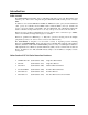
Introduction SIO4-104.485 The SIO4-104.485, Item Number 3543, is a PC/104 module that provides four, RS-422/485 serial interface ports. The board is designed using the XR16C554 UART, which provides a 16-byte FIFO. In addition to the standard XR16C554 UART, the XR16C854 (‘SE’ option) and the OX16C954 (‘SN’ option) are available. Both UARTS feature enhanced FIFOs (128 byte transmit and receive) and both maintain compatibility with the XR16C554.
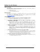
Before You Get Started What’s Included The SIO4-104.485 is shipped with the following items. If any of these items is missing or damaged please contact Sealevel for replacement. • SIO4-104.485 Adapter • Sealevel SeaCOM Software CD Optional Items Depending upon your application, you are likely to find one or more of the following items useful for interfacing the SIO4-104.485. All items can be purchased from our website (http://www.sealevel.com/) or by calling 864-843-4343.
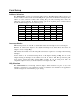
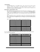
Card Setup Address Selection The SIO4-104.485 occupies 16 consecutive I/O locations. The DIP-switch (SW1) is used to set the base address for these locations and the IRQ mode options. Be careful when selecting the base address as some selections conflict with existing PC ports. The following table shows the addressing options available. If different address options are required, please contact Sealevel Systems Technical Support about a custom option.
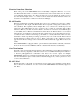
Clock Modes The SIO4-104.485 utilizes a 14.7456 MHz oscillator. This is eight times faster than the standard COM: port oscillator, which typically is 1.8432 MHz. This allows the adapter to achieve a maximum data rate of 921.6Kbps. The following sections outline the baud rate calculations and instructions for achieving your desired baud rate. Baud Rates and Oscillator value The following table shows some common data rates and the rates you should choose to achieve them when using the SIO4-104.485.
Electrical Interface Selection Each of the ports on the SIO4-104.485 can be individually configured as RS-422, or as a two wire RS-485 interface. This is a software selectable feature and is found at Base+15. To enable a port for RS-422, simply write a ‘0’ to Base+15 (this is the power up default). To enable a port for two-wire RS-485 simple write a ‘1’ to Base+15. If the Sealevel Software Windows drivers are used, this is accomplished as a function of the Device Manager.
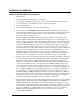
Software Installation Windows 98/ME/2000/XP Installation 1. Start Windows. 2. Insert the Sealevel Systems CD in to your CD drive. 3. If ‘Auto-Start’ is enabled for this drive the software will automatically launch. Otherwise, point your browser to the ‘Index.htm’ on the root directory of the CD 4. Select ‘Install Software’. 5. Select the Item Number for your adapter from the listing. 6. Select ‘Windows 98/ME/2000/XP’.
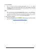
Linux Installation Refer to D:\software\seacom\Other\Linux\Linux.serial.readme (where D: = your CDROM driver letter) found on the Sealevel Systems CD. This file contains valuable information on installing your adapter in the various Linux releases. Also in this sub-directory is the Linux SerialHOWTO. These files explain typical Linux serial implementations, as well as informing the user to Linux syntax and preferred practices. QNX Refer to D:\software\seacom\Other\QNX6\Install.
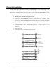
Physical Installation Extreme care should be taken when installing the SIO4-104.485 to avoid causing damage to the connectors. After the adapter is installed, connect your I/O cable to P4.. Refer to Card Setup for information on setting the address and jumper options before inserting the SIO4-104.485 onto the stack. Do not install the Adapter in the machine until the software has been fully installed. 1. Turn off power. Disconnect the power cord. 2. Gently insert the SIO4-104.
Physical Connection The port signals for the SIO4-104.485 are physically connected via a 40-pin box header. The following table shows connector P4’s pin-out. Port 4 3 2 1 P4 1 3 5 7 9 10 12 14 16 18 19 21 23 25 27 28 30 32 34 36 Signal Name RS-422 RX4+ RX4 TD4 TD4+ GND4 GND3 TD3+ TD3RX3RX3+ RX2+ RX2TD2TD2+ GND2 GND1 TD1+ TD1RX1RX1+ Signal Name RS-485 DATA4+ DATA4- GND4 GND3 DATA3DATA3+ DATA2+ DATA2- GND2 GND1 DATA1DATA1+ All pins not listed are no connects. © Sealevel Systems, Inc.
Available for use with the SIO4-104.485 are the CA228, the CA110/CA143, and the CA222/TB10 combination cables. These cables terminate the SIO4-104.485 40-pin header to four DB9M connectors. This termination provides the standard DB9 pin out for RS-232 (EIA/TIA574) in RS-232 mode. The following table illustrates the DB9 pin out when using any of these optional cables.
Electrical Characteristics Specifications RS-422/485 Transceiver • • • • • • • • • • • • • Bidirectional Transceiver Meet or Exceed the Requirements of ANSI Standards TIA/EIA-422-B and TIA/EIA-485-A and ITU Recommendations V.11 and X.27 Designed for Multipoint Transmission on Long Bus Lines in Noisy Environments 3-State Driver and Receiver Outputs Individual Driver and Receiver Enables Wide Positive and Negative Input/Output Bus Voltage Ranges Driver Output Capability . . .
Appendix A - Troubleshooting Following these simple steps can eliminate most common problems. 1. Install software first. After installing the software then proceed to Physical Installation section of the manual. 2. Identify all I/O adapters currently installed in your system. This includes your on-board serial ports, controller cards, sound cards etc. The I/O addresses used by these adapters, as well as the IRQ (if any) should be identified. 3.
Appendix B - How To Get Assistance Begin by reading through the Troubleshooting Guide in Appendix A. If assistance is still needed please see below. When calling for technical assistance, please have your user manual and current adapter settings. If possible, please have the adapter installed in a computer ready to run diagnostics. Sealevel Systems provides an FAQ section on its web site. Please refer to this to answer many common questions. This section can be found at http://www.sealevel.com/faq.
Appendix C – Electrical Interface RS-422 The RS-422 specification defines the electrical characteristics of balanced voltage digital interface circuits. RS-422 is a differential interface that defines voltage levels and driver/receiver electrical specifications. On a differential interface, logic levels are defined by the difference in voltage between a pair of outputs or inputs.
Appendix D - Asynchronous Communications Serial data communications implies that individual bits of a character are transmitted consecutively to a receiver that assembles the bits back into a character. Data rate, error checking, handshaking, and character framing (start/stop bits) are pre-defined and must correspond at both the transmitting and receiving ends. Asynchronous communications is the standard means of serial data communication for PC compatibles and PS/2 computers.
Appendix E – Silk Screen – 3543 PCB © Sealevel Systems, Inc. - 16 - SIO4-104.
Warranty Sealevel's commitment to providing the best I/O solutions is reflected in the Lifetime Warranty that is standard on all Sealevel manufactured products. We are able to offer this warranty due to our control of manufacturing quality and the historically high reliability of our products in the field. Sealevel products are designed and manufactured at its Liberty, South Carolina facility, allowing direct control over product development, production, burn-in and testing. Sealevel Systems, Inc.