SIO-104+2 Users Manual Part # 3502 Sealevel Systems, Inc. PO Box 830 Liberty, SC 29657 USA Telephone: 864.843.4343 Fax: 864.843.3067 www.sealevel.
Contents INTRODUCTION ....................................................................................................................................................... 1 OVERVIEW ................................................................................................................................................. 1 WHAT’S INCLUDED .................................................................................................................................... 1 OPTIONAL ACCESSORIES .......
Introduction Introduction Overview The SIO-104+2 series provides the ultimate serial connection for your PC/104 application. The SIO-104+2 when configured in the RS-422/485 mode provides an interface capable of long length, high-speed communications, or when configured in the RS-232 mode provides a standard RS-232C interface that is fully compatible all popular modem software, network operating systems software, and mouse drivers. What’s Included The SIO-104+2 is shipped with the following items.
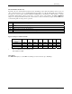
Card Setup Card Setup The SIO-104+2 contains two DIP-Switches and a jumper strap for each port, which must be set for proper operation. Switches SW1A and SW2A Address Selection Each port on the SIO-104+2 occupies eight consecutive I/O locations. A DIP-switch is used to set the base address for these locations. SW1A sets the I/O address for port 1 and SW2A sets port 2. The following table shows the addressing options available.
Card Setup Interrupt Modes DIP-Switch positions ‘S’ and ‘M’ on switches SW1A and SW2A select the interrupt mode for each port. Each port must be set in the correct mode to insure proper operation. With the ‘S’ selected, the adapter is in a (S)hared interrupt mode, which allows more than one port to access a single IRQ. Any two or more ports can share a common IRQ by placing the jumpers on the same IRQ setting and setting the appropriate selections at E1and E2.
Card Setup Switches SW1B and SW2B RS-485 Enable Modes (SW1B and SW2B position 1) RS-485 is ideal for multi-drop or network environments. RS-485 requires a tri-state driver that will allow the electrical presence of the driver to be removed from the line. The driver is in a tri-state or high impedance condition when this occurs. Only one driver may be active at a time and the other driver(s) must be tri-stated.
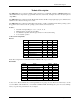
Card Setup Line Termination (Position 4-9) Typically, each end of the RS-485 bus must have line-terminating resistors (RS-422 terminates at the receive end only). A 120-ohm resistor is across each RS-422/485 input in addition to a 1K-ohm pull-up/pull-down combination that biases the receiver inputs. Switches SW1B and SW2B allows customization of this interface to specific requirements. Each jumper position corresponds to a specific portion of the interface.
Installation Installation Operating System Installation Windows 95/98/ME/NT/2000/XP Do not install the adapter in the machine until the software has been fully installed. 1. Start Windows. 2. Insert the Sealevel Systems CD in to your CD drive. 3. If ‘Auto-Start’ is enabled for this drive the software will automatically launch. 4. Otherwise, point your browser to the ‘Index.htm’ on the root directory of the CD 5. The next step is to select ‘Install Software’. 6.
Installation Linux Refer to D:\software\seacom\Other\Linux\Linux.serial.readme (where D: = your CDROM driver letter) found on the Sealevel Systems CD. This file contains valuable information on installing your adapter in the various Linux releases. Also in this sub-directory is the Linux SerialHOWTO. This series of files explains typical Linux serial implementations, as well as informing the user to Linux syntax and preferred practices. QNX Refer to D:\software\seacom\Other\QNX6\Install.
Technical Description Technical Description The SIO-104+2 series provides the ultimate serial connection for your PC/104 application. SIO-104+2 utilizes the 16850 UART. These chip features programmable baud rates, data format, interrupt control and 128 Byte input and output FIFOs. The SIO-104+2 when configured with the RS-422/485 interface will allow long length, high-speed communications suitable for data collection and shop floor control.
Specifications Specifications Environmental Specifications Specification Temperature Range Humidity Range Operating 0º to 70º C (32º to 158º F) 10 to 90% R.H. Non-Condensing Storage -50º to 105º C (-58º to 221º F) 10 to 90% R.H. Non-Condensing Manufacturing All Sealevel Systems Printed Circuit boards are built to UL 94V0 rating and are 100% electrically tested. These printed circuit boards are solder mask over bare copper or solder mask over tin nickel.
Appendix A - Troubleshooting Appendix A - Troubleshooting 1. Identify all I/O adapters currently installed in your system. This includes your on-board serial ports, controller cards, sound cards etc. The I/O addresses used by these adapters, as well as the IRQ (if any) should be identified. 2. Configure your Sealevel Systems adapter so that there is no conflict with currently installed adapters. No two adapters can occupy the same I/O address. 3. Try the Sealevel Systems adapter with a unique IRQ.
Appendix B - How To Get Assistance Appendix B - How To Get Assistance Please refer to Troubleshooting Guide prior to calling Technical Support. 1. Begin by reading through the Trouble Shooting Guide in Appendix A. If assistance is still needed please see below. 2. When calling for technical assistance, please have your user manual and current adapter settings. If possible, please have the adapter installed in a computer ready to run diagnostics. 3.
Appendix C - Electrical Interface Appendix C - Electrical Interface RS-232 Quite possibly the most widely used communication standard is RS-232. This implementation has been defined and revised several times and is often referred to as RS-232-C/D/E or EIA/TIA-232-C/D/E. It is defined as “Interface between Data Terminal Equipment and Data Circuit- Terminating Equipment Employing Serial Binary Data Interchange”. The mechanical implementation of RS-232 is on a 25-pin D sub connector.
Appendix C - Electrical Interface Appendix D - Asynchronous Communications Serial data communications implies that individual bits of a character are transmitted consecutively to a receiver that assembles the bits back into a character. Data rate, error checking, handshaking, and character framing (start/stop bits) are pre-defined and must correspond at both the transmitting and receiving ends.
Appendix E - PC/104 Appendix E - PC/104 What is PC/104? The PC has become extremely popular in both general purpose (desktop) and dedicated (embedded) applications. Unfortunately the PC has been hampered by the large size required to maintain PC compatibility. PC/104 addresses this by optimizing the PC bus in a form factor designed for embedded applications. Briefly, the key differences between PC/104 and the standard “AT” or ISA bus computer are as follows: • Reducing the form factor, to 3.550 by 3.
Appendix F - Silk-Screen Appendix F - Silk-Screen Sealevel Systems SIO-104+2 Page 15
Warranty Warranty Sealevel's commitment to providing the best I/O solutions is reflected in the Lifetime Warranty that is standard on all Sealevel manufactured products. We are able to offer this warranty due to our control of manufacturing quality and the historically high reliability of our products in the field. Sealevel products are designed and manufactured at its Liberty, South Carolina facility, allowing direct control over product development, production, burn-in and testing. Sealevel Systems, Inc.