
User guide

© Sealevel Systems, Inc.
- 3 -
SIO-104+16.485 User Manual
Hardware Setup
Address Selection
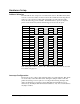
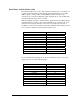
The SIO-104+16.485 occupies 16 consecutive I/O locations. The DIP-switch (SW1)
is used to set the base address for these locations. Be careful when selecting the base
address as some selections conflict with existing PC ports. The following table
shows the addressing options available. If different address options are required,
please contact Sealevel Systems Technical Support about a custom option.
Switch Settings
SW1-1
OFF
OFF OFF ON ON ON ON
SW1-2
OFF
ON ON OFF OFF ON ON
SW1-3
ON
OFF ON OFF ON OFF ON
Ports Addresses
Port 1
300
400 500 600 1500 3220 4220
Port 2
308
408 508 608 1508 3228 4228
Port 3
310
410 510 610 1510 3230 4230
Port 4
318
418 518 618 1518 3238 4238
Port 5
320
420 520 620 1520 3240 4240
Port 6
328
428 528 628 1528 3248 4248
Port 7
330
430 530 630 1530 3250 4250
Port 8
338
438 538 638 1538 3258 4258
Port 9
340
440 540 640 1540 3260 4260
Port 10
348
448 548 648 1548 3268 4268
Port 11
350
450 550 650 1550 3270 4270
Port 12
358
458 558 658 1558 3278 4278
Port 13
360
460 560 660 1560 3280 4280
Port 14
368
468 568 668 1568 3288 4288
Port 15
370
470 570 670 1570 3290 4290
Port 16
378
478 578 678 1578 3298 4298
Note: Setting SW1-1, SW1-2, and SW1-3 all to OFF disables the card, which may be useful
for troubleshooting purposes.
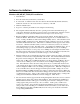
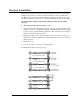
Interrupt Configuration
The board is set up to always share interrupts. There is a jumper labeled “PD” which
is located at (E1) on the SIO-104+16.485. Setting this jumper enables a 1K-ohm
pull-down (biasing) resistor required on one adapter when sharing interrupts. The
jumper should always be enabled on single SIO-104+16.485 installations (non-
shared mode). In multiple SIO-104+16.485 installations, only one board should have
the jumper enabled.