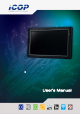
DM&P Vortex86MX+ Panel PC with 9” TFT LCD Model: PMX-090T-5A / PMX-090T-8A PMX-090T-5A-512 / PMX-090T-8A-512 (Revision 1.
Revision Date Version Description 2012/11/20 Version 1.
Copyright The information in this manual is subject to change without notice for continuous improvement in the product. All rights are reserved. The manufacturer assumes no responsibility for any inaccuracies that may be contained in this document. And makes no commitment to update or to keep current the information contained in this manual.
Table of Contents 1 2 3 General Information .............................................................................. 3 1.1 Product Description...................................................... 1 1.2 Product Specification ................................................... 2 1.3 Inspection standard for TFT-LCD Panel ........................ 4 1.4 Product Dimension ....................................................... 7 1.5 Ordering Information .........................................
1 .General Information 1.1 Product Description PMX-090T is an ultra-compact platform for the present demanding embedded and productive applications. It has new Vortex86MX SoC CPU which consumes only minimum power requirement when running at 1GHz, and DDR2 memory provides faster data transfer rate. By using 9” TFT LCD, PMX-090T becomes the perfect choice for a limited budget.
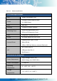
1.2 Product Specification Table 1-1 Product Specification CPU Board Specifications CPU DM&P Vortex86MX 1GHz L1:16KB I-Cache, 16KB D-Cache Cache L2: 256KB Cache BIOS AMI BIOS Memory 512MB/1GB DDR2 onboard Software programmable from Watchdog Timer 30.5u to 512 seconds x 2 sets LAN Integrated 10/100M Ethernet Audio HD Audio-Realtek ALC262 CODEC Compact Flash Type I / II slot Micro SD slot Internal Drives 1GB or 2GB Flash Memory onboard (Optional) RS-232/422/485 x 1 USB ports (Ver2.
Operating Humidity 0% ~ 90% relative humidity, non-condensing Dimensions 236.6 x 146 x 35mm (9.31 x 5.75 x 1.38 inches) Weight 468g Front Panel IP 65 Protection Certification CE / FCC / VCCI / Vibration LCD Specifications Display Type 9” TFT LCD Backlight Unit LED Display Resolution 2 1024(W) x 600(H) Brightness (cd/m ) 300 nits Contrast Ratio 500 : 1 Display Color 262, 144 Pixel Pitch (mm) 190.
1.3 Inspection standard for TFT-LCD Panel Table 1-2 Inspection Standard DEFECT TYPE LIMIT SPOT VISUAL DEFECT FIBER INTER NAL POLARIZER BUBBLE Mura φ<0.15mm Ignore 0.15mm≦φ≦0.5mm N≦4 0.5mm<φ N=0 0.03mm
[Note 1] W : Width[mm], L : Length[mm], N : Number, φ: Average Diameter. 1. White / Black Spot 2. Polarizer Bubble Fig 1-1 Fig 1-2 [Note 2] Bright dot is defined through 6% transmission ND Filter as following.
[Note 3] C Area: Center of display area O Area: Outer of display area [Note 4] Judge defect dot and adjacent dot as following. Allow below (as A, B, C and D status) adjacent defect dots, including bright and dart adjacent dot. And they will be counted 2 defect dots in total quantity.
1.
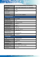
1.5 Ordering Information Table 1-3 Ordering Information PART NUMBER DESCRIPTION PMX-090T-5A 9” Panel PC w/1GB DDR2 / 2USB / Line-Out / LAN / COM / CF / MicroSD / Power Adapter PMX-090T-8A 9” Panel PC w/1GB DDR2 / 2USB / Line-Out / LAN / COM / CF / MicroSD / 8-35 DC Support PMX-090T-5A-512 9” Panel PC w/512MB DDR2 / 2USB / Line-Out / LAN / COM / CF / MicroSD / Power Adapter PMX-090T-8A-512 9” Panel PC w/512MB DDR2 / 2USB / Line-Out / LAN / COM / CF / MicroSD / 8-35 DC Support 1.
2 .System Installation 2.
2.2 Connector Summary Table 2-1 Summary Table Nbr Description Type of Connections Pin nbrs. J1 CF Master/Slave Switch Slide Switch ON/OFF J3 USB External USB Connector 6-pin J4 USB External USB Connector 6-pin J5 USB (Optional) 2.0mm 5-pin wafer 5-pin J8 PS/2 Keyboard 2.54mm 5-pin box header 5-pin J9 PS/2Keyboard External Mini DIN Socket 6-pin J10 COM2(RS232/422/485) External D-Sub Male Connector 9-pin J14 VGA 2.
2.
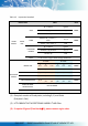
J14: VGA J31: 4-Wires Touch connector Pin # Signal Name GND 1 Y- 4 GND 2 X- B OUT 6 GND 3 Y+ 7 HSYNC 8 GND 4 X+ 9 VSYNCD 10 GND Pin # Signal Name Pin # Signal Name 1 R OUT 2 3 G OUT 5 J24: MIC-IN J32: USB (WiFi Optional) Pin # Signal Name Pin # Signal Name Pin # Signal Name 1 MICVREF 1 VCC 2 USBD2- 2 GND 3 USBD2+ 4 GND 3 GND 5 GND 6 GND 4 MIC-IN PWR: Power Connector (5A) J25: COM3 (TX, RX) Pin # Signal Name Pin # Signal Name 1 +5V 1 GND 2
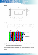
2.4 External I/O Overview { PMX-090T-8A / PMX-090T-8A-512 } Fig 2-2 PMX-089T-8A I/O overview { PMX-090T-5A / PMX-090T-5A-512 } Fig 2-3 PMX-090T-5A I/O overview {Note} 1. Wireless is optional 2.
2.
J10: COM1 RS232/422/485 (Change setting by BIOS) RJ45 Pin # Signal Name Pin # Signal Name 1 DCD1/422TX-/RS485- 2 RXD1/422TX+/RS485+ 3 TXD1 / 422RX+ 4 DTR1 / 422RX- 5 GND 6 DSR1 7 RTS1 8 CTS1 9 RI1 Pin # Signal Name Pin # Signal Name 1 FTXD+ 2 FTXD- 3 FRXIN+ 4 NC 5 NC 6 FRXIN- 7 NC 8 NC 15 PMX-090T DM&P Vortex86MX+ Panel PC with 9” WSVGA TFT LCD
2.6 System Mapping Table 2-2 Technical Data Sheet Technical Data Sheet Product Name PMX-090T-8A DM171C Doc.No. QMT1000014R00 Product Description 9” Vortex86MX Panel PC with 1GB Doc.
FEBDB800-FEBDB8FF FEBDBC00-FEBDBCFF Standard Enhanced PCI Host Controller Standard Enhanced PCI Host Controller to USB to USB * * I/O Mapping I/O Address Owner Usage 0000h - 000Fh DMA 8237-1 0010h - 0017h COM 9 0020h - 0021h PIC 8259-1 * 0022h - 0023h Indirect Access Registers ( 6117D configuration port ) * 002Eh - 002Fh Forward to LPC BUS 0040h - 0043h Timer counter 8254 * 0048h - 004Bh PWM counter 8254 * 004Eh - 004Fh Forward to LPC BUS 0060h Keyboard / Mouse data port * 0061
0098h - 009Ch GPIO direction control * 00A0h - 00A1h PIC 8259-2 * 00C0h - 00DFh DMA 8237-2 * 00E0h - 00EFh DOS 4G Page access * 0170h - 0177h IDE1 (IRQ 15) * 01F0h - 01F7h IDE0 (IRQ 14) * 0220h - 0227h COM8 Forward to LPC BUS 0228h - 022Fh COM7 Forward to LPC BUS 0238h - 023Fh COM6 Forward to LPC BUS 0278h - 027Fh Printer port (IRQ 7, DMA 0) 02E8h - 02EFh COM4 (IRQ 11) 02F8h - 02FFh COM2 (IRQ 3) 0338h - 033Fh COM5 Forward to LPC BUS 0376h IDE1 ATAPI device control write only
IRQ Mapping IRQ# Description Usage IRQ0 System Timer * IRQ1 Keyboard Controller * IRQ2 Cascade for IRQ8 - 15 IRQ3 USB * IRQ4 Serial Port 1 * IRQ5 USB * IRQ6 Unassigned IRQ7 Ethernet 10/100M LAN * IRQ8 Real Time Clock * IRQ9 USB * IRQ10 USB * IRQ11 Audio * IRQ12 Mouse * IRQ13 Math Coprocessor * IRQ14 Hard Disk Controller#1 * IRQ15 Hard Disk Controller#2 * DMA Mapping DMA# Description Usage DMA0 DMA1 DMA2 Floppy Disk Controller DMA3 DMA5 DMA6 DMA7 19 PMX
2.7 Watchdog Timer There are two watchdog timers in PMX-089T, we also provide DOS, Linux and WinCE example for your reference. For more technical support, please visit: http://tech.icop.com.tw or download the PDF file: dmp.com.
3 .Driver Installation VGA The Vortex86MX processor is integrated RDC Display chip which is an ultra low powered graphics chipset with total power consumption at around 1-1.5 W. LAN The Vortex86MX+ processor is integrated 10/100Mbps Ethernet controller that supports both 10/100BASE-T and allows direct connection to your 10/100Mbps Ethernet based Local Area Network for full interaction with local servers, wide area networks such as the Internet.
Operating system support The PMX-089T provides the VGA and LAN drivers for Linux, Windows CE, Windows XP Professional, and Windows Embedded standard (XPE). (Linux can use with Compact Flash card only.) Please get the drivers from ICOP official website: tech.icop.com.tw PMX-089T also supports most of the popular Linux distributions, for more detail information, please visit DMP official website:dmp.com.tw/tech/vortex86mx 3.1 PMX-090T Development Note 1.
4. Go to the PCI/PnP and make the “PCI IDE BusMaster” is “Disable" < XP professional /Home /Embedded and Windows 2000 installation note > Please visit technical website to get more information: tech.icop.com.tw Please select ICOP “ICF Card” to supporting UDMA 2/4 Mode. 1. Get into the BIOS setup Utility 2. Go to the Advanced 3. Choose Primary IDE Pin Select: SD card 4.
3.2 BIOS Default setting If the system cannot be booted after BIOS changes are made, Please follow below procedures in order to restore the CMOS as default setting.
Warranty This product is warranted to be in good working order for a period of one year from the date of purchase. Should this product fail to be in good working order at any time during this period, we will, at our option, replace or repair it at no additional charge except as set forth in the following terms. This warranty does not apply to products damaged by misuse, modifications, accident or disaster.