
User Manual

© Sealevel Systems, Inc.
- 4 -
PIO-48.PC104 User Manual
Card Setup
Address Selection
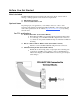
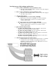
The PIO-48.PC104 occupies 8 consecutive I/O locations. The DIP-switch (S1) is
used to set the base address for these locations and the IRQ mode options. Be careful
when selecting the base address as some selections conflict with existing PC ports.
The following table shows several examples that usually do not cause a conflict.
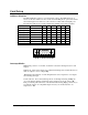
A9 A8 A7 A6 A5 A4
Hex Address
Binary
1 2 3 4 5 6
100-107 01 0000 xxxx On Off On On On On
180-187 01 1000 xxxx On Off Off On On On
200-207 10 0000 xxxx Off On On On On On
280-287 10 1000 xxxx Off On Off On On On
300-307 11 0000 xxxx Off Off On On On On
380-387 11 1000 xxxx Off Off Off On On On
3A0-3A7 11 1010 xxxx Off Off Off On Off On
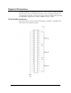
Interrupt Modes
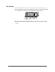
DIP-Switch positions ‘S’ and ‘M’ on switch S1 selects the interrupt mode for each
adapter.
With the ‘S’ selected, the adapter is in a (S)hared interrupt mode, which allows more
than one adapter to access a single IRQ.
‘M’ indicates the inclusion of a 1K-ohm pull-down resistor required on one adapter
when sharing interrupts.
Set the switch to ‘S’ for shared interrupt mode on all adapters sharing an IRQ. On
one of the adapters sharing an interrupt set the switches for both ‘S’ and for ‘M’.
This provides the pull-down resistor circuit that makes sharing IRQs possible. If you
are using more than one compatible adapter in a bus you should only have one
adapter set to ‘M’.
1 2 3 4 5 6 7
ON
8
987654 MS