PIO-48.PC104 User Manual Part Number 3701 www.sealevel.com PO Box 830 Liberty, SC 29657 864.843.
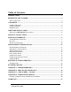
Table of Contents INTRODUCTION......................................................................................................................... 1 BEFORE YOU GET STARTED................................................................................................. 2 WHAT’S INCLUDED ...................................................................................................................... 2 CARD SETUP ........................................................................................
Introduction The PIO-48.PC104 part number 3701 digital I/O interface provides 48 channels of buffered drive digital I/O emulating 8255 mode zero. The PIO-48.PC104 can be utilized for a variety of control and automation applications including control and monitoring of TTL devices (e.g. LEDs, small solenoids, small relays) and interfacing to solid-state relay racks (SSRs) for high-power AC or DC loads. The PIO-48.
Before You Get Started What’s Included The PIO-48.PC104 is shipped with the following items. If any of these items is missing or damaged please contact Sealevel for replacement. PIO-48.PC104 Adapter Sealevel SeaI/O Software CD Optional Items Depending upon your application, you are likely to find one or more of the following items useful for interfacing the PIO-48.PC104 to real-world signals. All items can be purchased from our website (http://www.sealevel.com) or by calling 864-843-4343.
For high-current, high-voltage applications: IDC 50 to IDC 50 Pin Ribbon Cable (Part Number CA167) − 40” cable connects the PIO-96.PCI to solid-state relay racks equipped with 50-pin header interface. IDC 50 to IDC 50 Pin Ribbon Cable (Part Number CA135) − 40” cable connects the PIO-96.PCI to solid-state relay racks equipped with 50-pin edge connector. Solid-State Relay Racks: • Quad six position relay rack (Part Number PB24HQ) − Relay rack can accept up to six QSSRs for a total of 24 channels.
Card Setup Address Selection The PIO-48.PC104 occupies 8 consecutive I/O locations. The DIP-switch (S1) is used to set the base address for these locations and the IRQ mode options. Be careful when selecting the base address as some selections conflict with existing PC ports. The following table shows several examples that usually do not cause a conflict.
IRQ Selection IRQ3 IRQ15 IRQ12 IRQ11 IRQ10 IRQ9 IRQ7 IRQ5 IRQ4 The PIO-48.PC104 has an interrupt selection jumper, which should be set prior to use, if an interrupt is required by your application software. Consult the user manual for the application software being used to determine the proper setting. Note: The supplied driver for Windows and does not require, nor does it support interrupts. It is recommended that this jumper be removed to prevent any resource conflicts. © Sealevel Systems, Inc.
Software Installation Windows 98/ME/2000/XP Installation 1. Start Windows. 2. Insert the Sealevel Systems CD in to your CD drive. 3. If ‘Auto-Start’ is enabled for this drive the software will automatically launch. Otherwise, point your browser to the ‘Index.htm’ on the root directory of the CD 4. Select ‘Install Software’. 5. Select the Part Number for your adapter from the listing. 6. Select ‘Windows 98/NT/ME/2000/XP’.
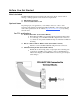
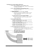
Physical Installation Extreme care should be taken when installing the PIO-48.PC104 to avoid causing damage to the connectors. After the adapter is installed, connect your I/O cables to P2 and P5. Please note these headers are keyed so that pin 1 of the cable matches pin 1 of the connector. Refer to Card Setup for information on setting the address and jumper options before inserting the PIO-48.PC104 onto the stack. Do not install the Adapter in the machine until the software has been fully installed. 1.
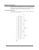
Digital I/O Interface The PIO-48.PC104’s 48 digital I/O channels are accessed via two industry-standard 50-pin header connectors. Each header provides 24 bits of digital I/O divided into two eight-bit ports and two four bit ports for upper and lower nibble. Each port may be individually configured via software command as input or output.
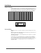
Pull Ups Eight resistors are installed to provide pull-ups to the input ports. These are installed on all ports. The pull-up resistors are rated at 10K ohms. Figure 4 below provides the resistors and corresponding port. The resistors ensure that no line is floating which is not connected. This provides consistent biasing on all un-terminated lines. © Sealevel Systems, Inc.
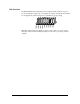
Physical Connection The port signals for the PIO-48.PC104 are physically connected via two 50-pin box headers. P5 provides the connections for ports A1-C1 and P2 provide the connections for A2-C2. These headers are compatible with the industry standard 50pin ribbon/IDC type cabling. This allows for a direct cabling connection between the PIO-48.PC104 and a Solid State Relay Rack (i.e. PB-8. PB-16, PB-24 etc.) The following table shows the correlation between the port addresses and the 50-pin connections.
Programming the PIO-48.PC104 Sealevel’s SeaI/O software is provided to assist in the development of reliable applications for the Sealevel Systems family of digital I/O adapters. Included on the SeaI/O CD are driver functions for use in accessing the I/O as well as helpful samples and utilities. Programming for Windows The SeaI/O API (Application Programmer Interface) provides a variety of useful high-level function calls implemented in a Windows dynamic link library (DLL).
Presetting an Output Port Each port has an output register associated with it. This register may be written and retains its value whether the port is configured as an input or an output. To preset the value of an output port the program should write to the port when it is configured as an input then configure it as an output. Writing the Outputs The outputs are active high. Writing a one (1) corresponds to 5V while writing a zero (0) corresponds to 0V, at the output.
I/O Control Word Each port may be configured as either Input or Output. This is accomplished by writing the correct Control Word (CW) to the proper register.
Interrupt Control When enabled interrupts are generated on port bit A0 of each port (pin 47 on each 50 pin header), the port A0 must be set as an input. X = port number IRQENX IRQCX0 IRQCX1 interrupt enable Interrupt mode select table IRQCn1 0 0 1 1 Interrupt Read 1 = enabled 0 = disabled ( 0 on power up ) Interrupt mode select see table Interrupt mode select see table IRQCn0 0 1 0 1 INT Type Low level High level Falling edge Rising edge Reading the INTSTAT port (Base+5) clears any interrupt pending.
Electrical Characteristics The PIO-48.PC104 uses 74LS245 octal bi-directional transceivers to provide TTL input/output capabilities. Each bit is pulled to +5V through a 10K ohm pull-up resistor to insure each bit is at a known state when not driven. Specifications Inputs Logic High: Logic Low: Min 2VDC Max 0.8VDC Outputs Logic High: Logic Low: Min 2VDC @ 15 mA Max 0.55VDC @ 24 mA Recommended Operating Conditions Inputs: Inputs: Source: Sink: Min 0V Max 5.
Example Circuits © Sealevel Systems, Inc. - 16 - PIO-48.
Appendix A - Troubleshooting Following these simple steps can eliminate most common problems. Install software first. After installing the software then proceed to adding the hardware. This places the required installation files in the correct locations. Read this manual thoroughly before attempting to install the adapter in your system. Use Device Manager under Windows to verify proper installation.
Appendix B - How To Get Assistance Begin by reading through the Trouble Shooting Guide in Appendix A. If assistance is still needed please see below. When calling for technical assistance, please have your user manual and current adapter settings. If possible, please have the adapter installed in a computer ready to run diagnostics. Sealevel Systems provides an FAQ section on its web site. Please refer to this to answer many common questions. This section can be found at http://www.sealevel.com/faq.
Appendix C – Silk Screen – 3701 PCB © Sealevel Systems, Inc. - 19 - PIO-48.
Appendix D - Compliance Notices Federal Communications Commission Statement FCC - This equipment has been tested and found to comply with the limits for Class A digital device, pursuant to Part 15 of the FCC Rules. These limits are designed to provide reasonable protection against harmful interference when the equipment is operated in a commercial environment.
Warranty Sealevel's commitment to providing the best I/O solutions is reflected in the Lifetime Warranty that is standard on all Sealevel manufactured products. We are able to offer this warranty due to our control of manufacturing quality and the historically high reliability of our products in the field. Sealevel products are designed and manufactured at its Liberty, South Carolina facility, allowing direct control over product development, production, burn-in and testing. Sealevel Systems, Inc.