Industrial Devices Corporation The Only Microstepping Drive with: Open Loop Stall DetectTM (OLSD™) Multi-SteppingTM Dynamic SmoothingTM Xtreme SmoothnessTM Motion Node User’s Manual P/N PCW-5181 Version 1.
Revision History Version: 1.0 April 2001 Industrial Devices Corporation (IDC) strives to maintain effective communication with all users and potential users of our products. If you have any questions or concerns regarding this technical manual or the product it covers, please contact: Industrial Devices Corporation 3925 Cypress Drive Petaluma, CA 94954 TEL: (800) 747-0064 FAX: (707) 789-0175 FROM OUTSIDE THE U.S. CALL (707) 789-1000 WEB SITE: www.idcmotion.com EMAIL: info@idcmotion.
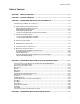
Table of Contents Table of Contents CHAPTER 1 - IMPULSE OVERVIEW ...............................................................................................1-1 CHAPTER 2 - SHIPPING CONTENTS .............................................................................................2-1 CHAPTER 3 - CONNECTING AND INSTALLING YOUR IMPULSE ...............................................3-1 A. CONNECTING A MOTOR TO THE IMPULSE .................................................................................
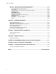
Table of Contents SECTION 1 - INTRODUCTION TO THE FP100 IMPULSE KEYPAD .........................................................5-1 SECTION 2 - CONFIGURING IMPULSE WITH AN IDC KEYPAD ...........................................................5-11 Configuring Impulse with the Keypad ..................................................................................5-12 Open a File ..........................................................................................................................
Chapter 1 - Impulse Overview Chapter 1 - Impulse Overview The Impulse is the latest microstepping drive from Industrial Devices Corporation and this innovative drive will move your applications with a combination of features previously unheard of in the motion control industry. The Impulse is a self-contained microstepping drive designed to operate permanent-magnet linear and rotary hybrid step-motors.
Chapter 1 - Overview This page intentionally left blank 1-2
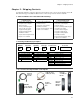
Chapter 2 - Shipping Contents Chapter 2 - Shipping Contents Your Impulse will arrive equipped as listed in section #1. If any parts or accessories are missing, please call IDC Customer Support at: (800) 747-0064. Sections 2 and 3 are provided as reference material. 1 - What You Will Receive if You Ordered the Following: Impulse + FP100 (or FP220) Keypad Impulse + FP100-RS485 (or FP220-RS485) Keypad Impulse Only 1. Impulse Microstepping Drive 1. Impulse Microstepping Drive 2.
Chapter 2 - Shipping Contents This page intentionally left blank 2-2
Chapter 3 - Connecting and Installing Your Impulse Chapter 3 - Connecting and Installing Your Impulse The purpose of this chapter is to provide information that will help you connect and install your Impulse drive in its intended application. The Impulse drive easily interfaces with a PC, PLC, Step & Direction Motion Controller, or IDC keypad. Block diagrams of several Impulse-based applications are shown below.
Chapter 3 - Connecting and Installing Your Impulse Read This Page Before Your Begin! CAUTION! • Always use caution when working with mechanical systems. Gears and screwdriven cylinders are capable of exerting tremendous force against an obstruction. • Always ensure that power to your system is OFF before performing any maintenance activity, or making any connections or adjustments. • Do not insert objects into the Impulse drive.
Chapter 3 - Connecting and Installing Your Impulse A. Connecting a Motor to the Impulse Connecting an IDC Motor The A+, A-, B+, and B- phase outputs power the motor windings. Connect motor wires to the motor connector (supplied) and plug the wired connector into the drive. Drawings below provide color codes for IDC motors. GND is internally connected to the earth pin on the power connector. This provides a convenient terminal for grounding the motor frame and a motor cable shield.
Chapter 3 - Connecting and Installing Your Impulse B. Serial Communication Connections Making RS-232/RS-485 Connections The standard Impulse drive uses a 3-wire implementation of RS-232C. The RX, TX, and COM lines are the serial signals supported. No hardware handshaking is required. Note that some RS-232C devices require handshaking, such as RTS and CTS.
Chapter 3 - Connecting and Installing Your Impulse Daisy-Chaining Impulse Drives Your Impulse also supports daisy chaining. The unit address (range 1-99) can be set via the keypad or in Application Developer. Rules for Daisy Chain Operation 1. Units on a daisy chain must be “device addressed’ (numbered) in order for communications to work properly. A unit’s address should increment upward as you move down the daisy chain from the PC (see illustration below). 2. Do not duplicate unit addresses. 3.
Chapter 3 - Connecting and Installing Your Impulse Troubleshooting RS-232C Communication Problems If communications between computer and Impulse are unsuccessful, one or more of the following procedures will usually solve the problem: 1. Host transmit (TX) must be connected to receive (RX) of the drive unit, and receive (RX) of the host must be connected to transmit (TX) of the drive. If communication fails, try switching connections on either the host or the drive. 2.
Chapter 3 - Connecting and Installing Your Impulse C. Connecting an IDC Keypad Two versions of IDC keypads can be used with the Impulse drive. The FP100 works only with the Impulse, while the FP220 can be used with the Impulse as well as IDC’s Smart Drives (see keypad-specific information below). COM PORT The COM PORT on the front panel of the Impulse is used for connecting either version of keypad. COM PORT I/O Power is applied to either version of keypad when power is connected to the Impulse.
Chapter 3 - Connecting and Installing Your Impulse D. Connecting AC Power There is no ON/OFF switch on the Impulse. AC power is applied by plugging the *power cord (included) into the connector on top of the Impulse. Input voltage must be in the range of 120 VAC ± 10%, single phase, 50/60 Hz, 500 VA max @ 4 Amps. Operation outside these specifications will result in reduced performance, drive faults, and may damage the drive.
Chapter 3 - Connecting and Installing Your Impulse F. Connecting Inputs and Outputs Connect your inputs and outputs to IDC’s 961/962 Indexer according to the information below. Schematics for Impulse I/O circuits can be found in Chapter 6, Hardware Reference Application Notes 1. On 961/2, ensure that Step/Direction and Differential Jumpers are installed (see 961/2 manual). 2. If using IDC P/N SS-I/O or SS-I/O-6 cable, cut one end of the cable if necessary (see table below for SS-I/O cable color-code).
Chapter 3 - Connecting and Installing Your Impulse G. Mounting the Impulse Drive This section includes installation requirements, Impulse dimensions, installing and removing mounting brackets, and mounting the Impulse on a DIN rail. Environmental and Installation Requirements • Operating Ambient Temperature: Max. 50º C (122º F) @ 4 Amps • Storage Temperature: Max. 65º C (149º F) • Not intended for use in humidity above 95% (non-condensing), or at altitudes greater than 3,048 meters [10,000 ft.
Chapter 3 - Connecting and Installing Your Impulse Impulse Dimensions Impulse with DIN-rail Mounting Bracket (P/N PCS-5111 TS 35 DIN RAIL 5.599 1.779 6.365 Impulse with Screw-type Mounting Bracket (P/N PCS-5110) 10-32 screw with .305'' head ∅ 6.000 5.599 1.779 6.365 1.
Chapter 3 - Connecting and Installing Your Impulse Inserting and Removing Mounting Brackets from the Impulse Both Impulse mounting brackets are interchangeable and each is inserted or removed according to the following procedures. No tools are required to insert a bracket, however a flat-bladed screwdriver is required for removal. If additional brackets are required, see Chapter 2, Shipping Contents, for part numbers. 1 Installation of Bracket (DIN Rail Bracket Shown) 1.
Chapter 3 - Connecting and Installing Your Impulse Impulse DIN-Rail Mounting The DIN-rail mounting system is a combination of 1) a removable mounting bracket, which locks the drive onto the DIN-rail (installation on previous page), plus 2) the DIN-rail hanger on the upper rear part of the housing that suspends the weight of the drive on the rail. Mounting Mounting the Impulse on the DIN-Rail 1. Hook the top of the DIN-rail hanger over the top of the DIN-rail. 2.
Chapter 3 - Connecting and Installing Your Impulse This page intentionally left blank 3-14
Chapter 4 - Configuring Impulse with Application Developer Chapter 4 - Configuring Impulse with Application Developer™ This chapter covers the installation and use of IDC’s Application Developer software to configure your Impulse drive. Installing Application Developer on Windows 95/98/2000/ME/NT 1. Place the IDC CD in your CD-ROM drive and click on the Start button. 2. Click on Run. 3.
Chapter 4 - Configuring Impulse with Application Developer Using Application Developer Application Developer’s graphic user interface allows you to configure and program your Impulse using an appropriately equipped computer. Upon starting Application Developer you will be given four options for beginning the configuration of your application (see window below). 1 2 3 page 4-5 4 Select from one of the following options to begin configuring your Impulse: 4-2 1. Upload Project.
Chapter 4 - Configuring Impulse with Application Developer Upload Project 1. Begin by clicking the Upload Project button on the Application Developer Startup window. You will see the Control Type Selection menu (shown right). 2. Configuration begins by selecting your Impulse from the list of Steppers. Click OK. 3. Select the Port you will use to connect the Impulse. Comm Port Settings (for reference only) RS-232C/RS-485 Baud Rate 19200 (fixed) Stop Bits 1 Data Bits 8 Parity None XON/XOFF Yes 4.
Chapter 4 - Configuring Impulse with Application Developer Launch Now This method of beginning Application Developer is typically used by more experienced users of IDC products. Select your Impulse version and press OK. You can now go directly to the Main Menu or tool bar buttons to configure the Impulse (see Fine-Tuning Your Application). Open an Existing Project If you want to open a project file which has been stored on disk (not in the Impulse), select Open an Existing Project.
Chapter 4 - Configuring Impulse with Application Developer Using the Project Wizard 1. Click the Project Wizard button on the Application Developer Startup window. • Select the product you are configuring, Impulse in this case, and click on Next. • The Wizard Navigator (left side of window) allows you to quickly locate your current position in the setup process. The column of boxes represents the parameter being configured. A box’s color represents its configuration status, i.e.
Chapter 4 - Configuring Impulse with Application Developer 3. Click Next and the first of three possible Mechanics setup windows will appear. The Mechanics window that appears depends on the selection made in the Select an IDC Mechanical System list. Mechanics window A (shown below) appears when a Motor Only is being configured. This window shows the IDC motor or user-defined file name in the Part # text input box, and the Motor Rotor Inertia (in kg-cm2) of the motor being configured. • Select Motor Only.
Chapter 4 - Configuring Impulse with Application Developer Mechanics window C will appear if you select Non-IDC Mechanics from the “system” list. • Enter your Total System Inertia (Load + Mechanics + Motor). • Select your Move Unit (steps, revs, mm, or inches) from the pulldown menu. • Enter your Distance Ratio (only if inches or mm are the selected Move Units). You cannot enter Distance Ratio if either steps or revs has been selected. C 4.
Chapter 4 - Configuring Impulse with Application Developer Discrete Inputs (see pulldown menu) Discrete Outputs (see pulldown menu) 6. When all parameters have been configured, click Next and the Accept window will appear. This display allows you to review the settings made earlier, or gives you an opportunity to return (Back button) to any parameter you may want to change. • When satisfied with the setup of your system, click on Accept.
Chapter 4 - Configuring Impulse with Application Developer 7. Your basic project file has now been configured but the four “Finish” steps must be completed in order to send the project file to the drive and probe the motor. • Click on Config. Comm Port (#1) and select the Port to which you are connecting the Impulse. Next, select a Unit Number (from 1 - 99) for the Impulse being configured. To test communication using the current setup, click on Test Connection. Click OK.
Chapter 4 - Configuring Impulse with Application Developer Fine-Tuning Your Application Your basic system setup parameters have been configured by the Project Wizard, and though the system is functional, your application will probably require further configuration and fine-tuning. The remainder of this chapter provides information on configuring your Impulse with Application Developer’s setup and I/O menus.
Chapter 4 - Configuring Impulse with Application Developer Motor • Motor Name - Select your motor from the list, or click on the Edit Motor button to create a custom motor file or edit an existing IDC motor file. • Electrical - These text input boxes display the electrical characteristics of the selected motor. If a text input box displays a zero (0), that particular electrical characteristic has not been configured as part of the motor file. To create or change a motor file, see Edit Motor.
Chapter 4 - Configuring Impulse with Application Developer Mechanics Move Unit and Total Inertia (kg-cm2) are displayed on this tab, but they are not editable parameters. Click on the Change Mechanical System/Units button to edit your mechanical parameters. • Change Mechanical System/Units - The text input-box parameters (in each available Setup Mechanical System window) are dependent upon the selection you make from the Select Mechanical System list.
Chapter 4 - Configuring Impulse with Application Developer Command The Command Tab allows you to configure the Command Signal and Jog Input parameters, and to select the level of Numeric Precision that Application Developer will use to build the project file. Command Signal Configuration • Drive Resolution - Enter the operating step resolution in integer multiples of four times the tooth count of the motor (50 tooth count x 4 = 200), or select a resolution from the scrollable list.
Chapter 4 - Configuring Impulse with Application Developer • Jog High (Jog High Speed) - Default = 2.00 (user-defined units) Numeric Precision • Select Standard to limit the decimal precision of accelerations, decelerations, velocities, and distances to the following: Accels and Decels: Velocities: Distances: #.x #.xx #.xxx (One decimal place) (Two decimal places) (Three decimal places) The Standard decimal precision is sufficient for most applications. Standard is the default setting.
Chapter 4 - Configuring Impulse with Application Developer X-Smoothness (Xtreme Smoothing™) The X-Smoothness tab is the most advanced low-speed tuning feature currently available on any microstepping drive. The benefits of low-speed smoothness are 1) reduced vibration, and 2) an increase in torque, which was typically lost to vibration before the arrival of the Impulse drive. Achieving this revolutionary smoothness is easily and quickly accomplished by following the simple procedure below.
Chapter 4 - Configuring Impulse with Application Developer X-Smoothness #2 Recommended values for M1 and M2 have been pre-configured for IDC motors, but we recommend that these settings be verified and adjusted if necessary by the following procedure. 5. 6. 7. 8. 9. Press the Run Test button. Move slider M1 to approximately 8,000. Move slider M2 left and right until the smoothest running condition is reached. Move slide M1 left and right until the smoothest running condition is reached. Press Stop Test.
Chapter 4 - Configuring Impulse with Application Developer Advanced (Advanced Tuning) The Advanced tab allows you to enable/disable and modify various advanced performance features of the Impulse drive. Note: Observe decrease in Gain when Multi-Stepping is Enabled. Anti-Resonance • Enable this feature by selecting the Enabled check box. Ensure that both Damping Gains are configured if Anti-Resonance is enabled.
Chapter 4 - Configuring Impulse with Application Developer Stall Detection • Select Stall Detection to enable the Open Loop Stall Detect™ encoderless stall detection feature. • Stall detection becomes active at velocities of 0.5 RPS and greater. Remember to perform a “Send All” command to send the modified project file to the drive. I/O Setup After configuring the Axis Setup parameters, the discrete inputs (4 ea.) and output (1 ea.) will need to be configured for your application.
Chapter 4 - Configuring Impulse with Application Developer Setup - Editing Stored Moves later in this chapter for more information on Home moves. Jog +: Activation of a Jog+ input will jog the motor at the acceleration rate specified by the Jog Accel parameter and the velocity specified by the current state of a Jog Speed input in the positive direction. If a Jog Speed input has not been configured, the motor is jogged at the velocity specified by the Jog-Low parameter.
Chapter 4 - Configuring Impulse with Application Developer Output Descriptions Brake: The Brake output is activated on any fault condition. This provides a control signal to engage a brake when the Impulse loses torque due to a fault. The Brake output also provides a polarity-configurable fault output since the dedicated fault output is fixed as an active high, sinking output. Note: The Brake output is not intended nor designed as a power source for a mechanical brake.
Chapter 4 - Configuring Impulse with Application Developer Stored Move Setup - Editing Stored Moves If your Impulse is equipped with the Motion Node option you will be able to access the Stored Move Setup menu shown below. The Impulse will store seven (7) moves which can be invoked through binary inputs, by serial commands (see Appendix B), or via the Run > Stored Move window. Moves are edited in the Stored Move Setup window via Edit > Stored Move or the Edit Stored Moves tool bar button.
Chapter 4 - Configuring Impulse with Application Developer Note: Homing is predicated on the assumption that the system is positioned somewhere between the EOT switches when the home move is invoked. If the system is initially outside the interval between the EOT switches, the homing routine will fail in one of two ways: (1) carriage will be driven against mechanical end-stop. (2) carriage will end up “homed” outside the interval between the EOT switches.
Chapter 4 - Configuring Impulse with Application Developer File Menu • Selecting New Project will take you to the Project Wizard. • The default file suffix is *.idc. • Project files may be stored on disk as DOS files. • All other selections under the File menu are generic to all Windows applications. Edit Menu • Stored Move and Motor File Editors, both discussed previously, can also be accessed from the menu bar.
Chapter 4 - Configuring Impulse with Application Developer Communications Menu • Use Send All to download a project file to the drive. A Send All toolbar button is also available. • Use Retrieve All to upload a project file from the drive for modification. • Project Update allows you to accelerate the configuration of multiple drives when all drives have the same setup configuration.
Chapter 4 - Configuring Impulse with Application Developer Run Menu • The Run > Stored Move menu is available only on drives equipped with the Motion Node option and can only be accessed from the menu bar. This menu allows you to view all stored move profiles and to run and stop each stored move. • No editing of moves is available on this menu. During the execution of any stored move, the Impulse ignores the step and direction inputs. Any activity on those inputs is completely lost.
Chapter 4 - Configuring Impulse with Application Developer View Menu • Select Configuration Text File to see your system configuration status. All configuration parameters are listed and may be viewed by scrolling the list. • Select Control Status for a quick look at current I/O configuration, motor position and velocity, fault history, and basic internal drive information (i.e. firmware version, etc.). • Click Drive Info for a look at hardware and firmware versions.
Chapter 4 - Configuring Impulse with Application Developer Updating Your Impulse Operating System: Your Impulse drive contains FLASH memory technology allowing the flexibility and convenience of upgrading the operating system using Application Developer and a PC RS232 or RS485 serial connection. The latest released Impulse operating system version is available for download at our web site http://www.idcmotion.com.
Chapter 4 - Configuring Impulse with Application Developer This page intentionally left blank 4-28
Chapter 5 - Configuring Impulse with an IDC Keypad Chapter 5 - Configuring Impulse with an IDC Keypad Section 1 of this chapter is intended primarily to familiarize new IDC keypad users with the FP100 Impulse Keypad, and we recommend this section be reviewed by those experienced with the FP220 keypad as well. If you are using an FP220 keypad (version 3.00 and above) to configure the Impulse, it is imperative that the keypad DIP-switches be set as shown on the next page.
Chapter 5 - Configuring Impulse with an IDC Keypad Keypad Hardware Features Adjusting Contrast On the back of the keypad there is a plastic potentiometer, adjustable with a flathead screwdriver. This is used to adjust the contrast on the LCD display. If the Impulse drive and keypad were purchased together, this adjustment has been made by IDC. Some adjustment may still be necessary to accommodate a variety of lighting conditions or viewing angles.
Chapter 5 - Configuring Impulse with an IDC Keypad Functions of the FP100 Keypad Keys F Keys (F1-F2-F3) Used as menu or sub-menu item selectors. 0-9 Keys Enters numbers directly, and letters when preceded by the ALPHA key. Menu Keys jogs RUN - Runs a program, RUN an axis, or accesses Test/ - Run stored moves, Debug probe functions. and jog the motor, warm-boot the drive, and enable/disable software EDIT - Edits Setup parameshutdown. ters and programs, lists programs, & resets position EDIT counter.
Chapter 5 - Configuring Impulse with an IDC Keypad Keypad Menu Structure Most operations using the keypad are menu-driven. A menu consists of a title bar on the top display line and as many as three options (or sub-menus) at a time on the bottom display line. Each option is displayed above one of the function keys, F1, F2, or F3. Press a function key to select the corresponding option.
Chapter 5 - Configuring Impulse with an IDC Keypad Apply Power to the Keypad Power is supplied to the FP100 keypad through its connection to the Impulse COM PORT. Note: If you are using an FP100-RS485, see Chapter 3, Section C for connection procedure. When power is first applied to the keypad (prior to any menu being selected) you should observe the display shown on the right.
Chapter 5 - Configuring Impulse with an IDC Keypad RUN Using the RUN Menus Press the RUN key to display the MOVE, PROBE, JOG, WMBOOT, and SHTDWN menus. −−−−−−↑ ↑ RUN ↓−−−−− MOVE PROBE JOG −−−−−−↑ ↑ RUN ↓−−−−− WMBOOT SHTDWN Run Stored Move (MOVE) Note: The MOVE feature is available only if you purchased the optional Motion Node version of the Impulse −−−↑ ↑ RUN MOVE ↓−− 1 2 3 RUN > MOVE allows you to select and run one of the seven stored moves in the drive.
Chapter 5 - Configuring Impulse with an IDC Keypad EDIT Using the EDIT Menus Press the EDIT key to display the FILE, SETUP, MOVE, and UNIT# menus. −−−−−−↑ ↑ EDIT ↓−−−−− FILE SETUP MOVE −−−−−−↑ ↑ EDIT ↓−−−−− UNIT# File Menu (FILE OPTIONS) The FILE menu allows you to select, save, and name or rename your project files. EDIT > FILE −−− FILE OPTIONS −−− OPEN SAVE RENAME Opening a Project File This option allows you to select one of eight (8) stored project files.
Chapter 5 - Configuring Impulse with an IDC Keypad Renaming an Open Project File This option allows you to rename (or name) the currently-open project file. Project file names are entered using a combination of the ALPHA and numeric keys. Project file names consist of numeric digits and alphabet letters and are limited to 10 characters. Alphabet characters are accessed by pressing the ALPHA key and repeatedly pressing the numeric key until the desired letter is displayed on the screen.
Chapter 5 - Configuring Impulse with an IDC Keypad HELP Using the HELP Menu Versions • Press the HELP > VERSN (F2) for access to Operating System, Hardware, and Keypad versions (see examples on the right). • Press F1, F2, or F3 for respective version displays. • Press the ESC key to exit the HELP menu.
Chapter 5 - Configuring Impulse with an IDC Keypad COPY Using the COPY Menu Downloading project files between keypads and Impulse or between keypad and PC can save a significant amount of time when configuring your drive with an FP100 keypad. Press COPY for the following two options: TO PAD COPY FRM PAD FROM PAD This option allows you to send the currently open project file to the drive. Answering YES to the send prompt will send the open project file and overwrite the current setup in the drive.
Chapter 5 - Configuring Impulse with an IDC Keypad Section 2 - Configuring Impulse with an IDC Keypad This chapter contains information and steps for developing an Impulse project file with the FP100 keypad. Configuring all parameters in the EDIT menu will ensure that your project file is setup correctly. The task of configuring your Impulse for a specific application consists of customizing a number of software parameters to match the mechanics of the system.
Chapter 5 - Configuring Impulse with an IDC Keypad Configuring Impulse with the Keypad Open a File Using the EDIT > FILE menu, open a project file. Using the EDIT > SETUP Menus to Configure the Impulse The EDIT > SETUP menus allow you to configure your motor, mechanical units, I/O, operating characteristics, and perform advanced tuning of your system for optimum performance.
Chapter 5 - Configuring Impulse with an IDC Keypad To Probe the Motor: 1. Return to the initial keypad display (no menu selected). 2. Press RUN > PROBE (F2). At the end of the 1 kHz tone, the motor has been probed. 3. Press ESC. 4. Continue configuring the EDIT Menu parameters if they have not been completely configured, or go to step 5. 5. Press COPY > FRM PAD (F3) to send the project file to the drive.
Chapter 5 - Configuring Impulse with an IDC Keypad Configuring Drive Resolution EDIT > SETUP > COMAND > D-RES - Drive Resolution 25000 1. Using the numeric keys, enter the operating step resolution. The valid range for drive resolution is 200 to 100,000 in increments of 200 (divisible integer of 4X the tooth count of the motor). 2. Press ESC. Configuring Stop Rate This option allows you to define the deceleration rate to be used when a STOP or EOT input is activated or the ESC key is pressed.
Chapter 5 - Configuring Impulse with an IDC Keypad MECHANICAL SETUP The MECH SETUP menu allows you to configure (enter) the mechanical units and gear ratio for your application. Once configured, your keypad will use these units in all display and position reporting modes. EDIT > SETUP > MECH MECH SETUP UNITS RATIO Configuring Mechanical Units (User Units) This option allows you to select the units of distance, velocity, and acceleration used in the system.
Chapter 5 - Configuring Impulse with an IDC Keypad MOTOR TUNING SETUP (X-Smoothness) Fine-tuning of the motor is recommended for all applications and should be accomplished before the motor load is connected. Fine-tuning produces extremely smooth performance at 2 rps and below and is accomplished by configuring the three X-Smoothness components (X-SM1, X-SM2, and XSM3).
Chapter 5 - Configuring Impulse with an IDC Keypad 4. Press ESC. 5. Press YES (F1) to save the new settings, or press NO (F3) to restore the original settings. Keep New Settings? YES NO Configure X-SM2 and X-SM3 using the same procedures as X-SM1 (i.e. VALUE, TEST SPEED, and FINE).
Chapter 5 - Configuring Impulse with an IDC Keypad Configuring Profiling Parameters EDIT > SETUP > ADVNCE > DYN-SM - PROFILING MULTI DYNSM DSGAIN MULTI (Multi-Stepping™) This option allows you to enable or disable Multi-Stepping™ feature. 1. Press MULTI (F1). 2. Using arrow keys, select ENABLED or DISABLED. 3. Press ESC. −−− Multi-Stepping −−− ↑ DISABLED ↓ DYNSM (Dynamic Smoothing™) This option allows you to enable of disable the Dynamic Smoothing™ feature. 1. Press DYNSM (F2). 2.
Chapter 5 - Configuring Impulse with an IDC Keypad Configuring Idle Mode Current Reduction Parameters Use this option to set the Idle Mode current-reduction parameters (TIMEOUT and %RED). TIMEOUT sets the Idle Mode current reduction period in seconds. When the TIMEOUT period has elapsed, the commanded motor current will be reduced by the percentage defined in EDIT > SETUP > ADVNCE > I-IDLE > %RED. Full current is restored on the next commanded step. The valid range for the timeout is 0 to 3600 seconds.
Chapter 5 - Configuring Impulse with an IDC Keypad I/O SETUP This option allows you to configure up to (4) digital inputs and one (1) digital output. EDIT - - - - I/O SETUP - - - INPUT OUTPUT POLAR > SETUP > I/O Configuring Inputs The input number (#1 - #4) is selected by using the right or left arrow key. The input function is selected by scrolling the list using the up or down arrow key. The INPUT menu consists of the inputs described in the table below.
Chapter 5 - Configuring Impulse with an IDC Keypad Configuring Outputs The output function is selected by using the up or down arrow key. The OUTPUT menu consists of the outputs described in the table below. Configurable Inputs UNDEFINED BRAKE MOVING [RESERVED] STALLED Input Description The output position has no function Activated on a fault Activated when receiving steps or the internal move engine is active Reserved for future use - acts as UNDEFINED Activated when the OLSD™ detects a stall 1.
Chapter 5 - Configuring Impulse with an IDC Keypad Move Menus - Using Stored Moves This feature is only available of your Impulse is equipped with the optional Motion Node. The MOVE menu allows you to edit the Stored-Move parameters (also see Edit > Stored Move menu in Application Developer). EDIT > MOVE - - - STORED MOVES - - PROFLE SCAN Stored-Move Profiles The PROFLE (profile) menu allows you to configure the seven (7) possible stored -move profiles executed by the internal move engine.
Chapter 5 - Configuring Impulse with an IDC Keypad Configuring Stored-Move Profiles There are five (5) stored move parameters to be configured: Acceleration, Deceleration, Velocity, Distance, and Move Type. 1. Press PROFLE (F1). 2. Using the up or down arrow key, select the Move # (1 - 7) to configured. 3. Using the right or left arrow key, select the move parameter to be configured. ←↑ Move #1 Decel ↓→ 0.0 RPS2 Note: Step 4 applies to Accel, Decel, Velcty, and PosDis. Step 5 applies to MvType.
Chapter 5 - Configuring Impulse with an IDC Keypad UNIT# This menu allows you to configure the unit number for use in RS232C daisy chains or RS485 buses. The valid range for unit numbers is 1 - 99. EDIT 1. > UNIT# - - - Unit Number - - 1 Using the numeric keys, enter the desired unit number for the drive. Very Important! - Send the File to the Drive When all setup parameters have been configured and the motor has been probed, use the COPY menu (COPY > FRM PAD) to send the project file to the drive.
Chapter 6 - Hardware Reference Chapter 6 - Hardware Reference Impulse Specifications Electrical Characteristics Power Requirements 120 VAC ±10% single phase, 50/60 Hz, 500 VA max @ 4 A Current Output Range 0.75 - 4.0 Amps Motor Inductance Range 2 - 80 mH Motor Resolution 25,600 Steps/Rev internal. Pre-scaled for the range 200 - 100,000 Motor Frame Size - NEMA 17 - 34 Step & Direction Inputs Input Voltage *5 VDC (see note at bottom) Input Current 5 - 15 mA Setup Time (Direction) 250 ns Max.
Chapter 6 - Hardware Reference Remote Mounting Your Keypad The keypad can easily be mounted and sealed to NEMA 4 specifications by using the included mounting gasket and 6-foot communication cable. Warning: Do not attach the gasket to the keypad. Attach the gasket with the adhesive side toward the mounting enclosure. A pressure-seal is formed between the gasket and the keypad, while the adhesive maintains the seal between the enclosure and the gasket.
Chapter 6 - Hardware Reference Keypad Mounting *Template *CAUTION - this is scaled-down version of the keypad template. Use this drawing only for dimensions and locations of mounting holes. The actual template is included with your keypad and may also be found at: http://www.idcmotion.com/support/index.html KEYPAD MOUNTING TEMPLATE CAUTION: Your Keypad will be damaged if mounting screws extend more than 0.2 inches into the keypad. E 3/16" CLEARANCE HOLES (4) CUT THESE HOLES FOR 6/32 CAPTIVE MOUNTING.
Chapter 6 - Hardware Reference Impulse I/O Schematics Digital Inputs +5V 4.99K IN1/IN2 IN1_BUF +5V AM26LS32 Inputs 1, 2 1K 1K COM COM TO COMMON Impulse internal external +5V 1K CMPD914 IN3/IN4 LIMIT SWITCH 4.02k COM COM Impulse internal external Digital Output PULL-UP +5V, +12V, or 24V +ANA RELAY COIL SOURCING INPUT 10K OUT OR MMBT2222ALT1 OUT 2.
Chapter 6 - Hardware Reference Step, Direction, and Shutdown Inputs Application Notes: 1.When wiring TTL signals to other manufacturer’s indexers, the Step TTL command signals from the controller should be wired to Step +, the Direction signal to Dir +, and the Shutdown signal to SD + (Step -, Dir -, and SD - should not be connected). Remember to connect commons. 2.Activating the Shutdown input (logic low) disables the drive amplifier and de-energizes the motor.
Chapter 6 - Hardware Reference Using IDC Position Sensors as EOT Limit Switches with the Impulse Four IDC position sensors may be used as EOT limit switches with the Impulse. Connection information for all four sensors is provided below. +5V PSR-2 +5V • The PSR-2 position sensor is a normally closed Reed Switch and must be connected to two (2) separate inputs, as shown here. This leaves two (2) inputs for move selects, which allows for the selection of three (3) stored moves.
Chapter 6 - Hardware Reference Optional Accessories for Your Impulse Impulse I/O Accessories Accessory (P/N & Description) DB25BO Screw Terminal Breakout Board Dimensions: 2.0L x 1.0W x 0.8D See page next page for connection information. SS-IO SS-IO-6 25-pin D-Shell I/O cable that connects Impulse to other devices or PLC SS-IO is 2 ft. SS-IO-6 is 6 ft. See the next page for wire color codes SS-RS232 Cable for connecting Impulse to PC (9-pin Comm.
Chapter 6 - Hardware Reference DB25BO Screw Terminal Breakout Board When connected to the Impulse, the DB25BO terminals will match the pinouts of the 25-pin connector as shown below.
Chapter 6 - Hardware Reference Impulse-Applicable IDC Motors S12 Hybrid Step Motor (BOTH ENDS) Electrical Specs. Continuous Stall Torque S12T oz-in [N-m] 35 [0.25] Recommended Current/Phase Amps 1.0 Winding Resistance @ Ambient Ohms 5.52 Inductance mH Max. Winding Temperature 8.8 °F [°C] 212 [100] S12T Mechanical Specs. Rotor Inertia 2 2 Axial Shaft Load lbs [N] lbs [N] 5 [22] lbs [kg] 0.66 [0.3] degrees 1.
Chapter 6 - Hardware Reference S21, S22, S23 Hybrid Step Motor Specifications .003 A .002 A .002 A Electrical Specs. S21T Continuous Stall Torque oz-in [N-m] S21V 65 [0.46] S22T S22V 100 [0.71] S23T S23V 125 [0.88] Recommended Current/Phase Amps 1.05 2.1 1.5 3.0 1.75 3.5 Winding Resistance @ Ambient Ohms 5.4 1.35 4.8 1.2 4.4 1.1 mH 18 4.5 18 4.5 18 4.5 Inductance Max. Winding Temperature °F [°C] 212 [100] Mechanical Specs.
Chapter 6 - Hardware Reference S32, S33 Hybrid Step Motor Specifications .003 A 1/2-14NPS 0.23/0.21 THRU (4) ON A 3.875 B.C. .001 A Electrical Specs. Continuous Stall Torque oz-in [N-m] S32T S33T 300 [7.1] 400 [5.3] Recommended Current/Phase Amps 2.8 3.5 Winding Resistance @ Ambient Ohms 1.03 .96 Inductance mH Max. Winding Temperature °F [°C] Mechanical Specs. oz-in-s2 [kg-m2] Rotor Inertia Axial Shaft Load lbs [N] Radial Shaft Load @ 0.
Chapter 6 - Hardware Reference P21, 22 Hybrid Step Motor Specifications 45 B 2.22 .02 .70 .02 .002 .002 A C .20 .31 .02 4X .02 2.22 .02 .205 .010 THRU EQ SP AS SHOWN ON A 2.625 BC .010 A B .02 8X #24 AWG CONDUCTOR CABLE X 144.0 LONG MIN WITH FOIL SHIELD AND DRAIN APPROXIMATE SIZE .23 DIA 30 180 .2500 .2495 .001 A C .004 A C .005 .02 1.11 .03 .02 1.500 .219 1.11 .81 .06 CE 3X 90 .2500 .2495 .001 A C .004 A .75 A .04 P21: 2.205 MAX P22: 3.
Chapter 6 - Hardware Reference P/K 31, 32, 33Step Motor Specifications Electrical Specs. Continuous Stall Torque oz-in [N-m] Recommended Current/Phase 920 [6.5] 1260 [8.9] 2.9 3.3 4.0 mH 14 30 25 212 [100] 212 [100] 212 [100] P31V P32V P33V Mechanical Specs. oz-in-sec Axial Shaft Load Radial Shaft Load @ 0.5 inches Motor Weight Step Angle (full step) EQ and EM Encoder Cables P33V 450 [3.2] °F [°C] Rotor Inertia P32V Amps Inductance Max. Winding Temperature P31V .0202 .038 .
Chapter 6 - Hardware Reference This page intentionally left blank 6-14
Chapter 7 - Troubleshooting the Impulse Chapter 7 - Troubleshooting the Impulse This chapter covers common faults, their possible causes and remedies. Also include in this chapter are Impulse Limits Tables for a variety of operational parameters, e.g. the Acceleration/ Deceleration/Velocity Limits Table. The Impulse drive detects and resolves fault conditions. Faults are signaled by either a steady red or flashing red LED on the front panel. A solid green LED indicates normal operation.
Chapter 7 - Troubleshooting Your Impulse 7-2 Symptom Possible Causes Possible Remedies The keypad is blank, but the backlight is on. You have an older keypad that requires new firmware. The Impulse requires a keypad with Version 3.00 firmware or higher. Call IDC for a free firmware upgrade to your keypad. The keypad is blank and the backlight is off. The keypad is not receiving a good +5VDC signal. Check wiring, verify that the +5VDC is between 4.8 and 5.2V.
Chapter 7 - Troubleshooting the Impulse Symptom Possible Causes Possible Remedies 6 LED flashes (Over Temperature Fault) Internal Fan or Heatsink Tunnel is clogged or restricted (internal temp. has exceeded 68° C (154° F). Remove obstruction (clean by blowing shop air through the tunnel. Ambient air in cabinet is too hot. The Impulse can produce 20 Watts of heat. If multiple units are installed next to each other, the cabinet must be adequately ventilated to remove heat.
Chapter 7 - Troubleshooting Your Impulse This page intentionally left blank 7-4
Chapter 8 - Product Support & Warranty Information Chapter 8 - Product Support Factory Authorized Distributors IDC has more than 45 factory-trained and authorized automation technology distributors located throughout North America, Western Europe, and the Pacific Rim. Each has been selected for their technical expertise, their local market knowledge, and exemplary business practices. They are ready to assist you in applying Industrial Devices’ systems, as well as other complementary equipment.
Chapter 8 - Product Support & Warranty Information Warranty & Repairs Industrial Devices Corporation (IDC) warrants this product to be free of defects in material and workmanship for a period of two (2) years from the date of shipment to the end user. Products that have been improperly used or damaged, in the opinion of IDC, are not subject to the terms of this warranty. IDC maintains a repair facility at its factory in Petaluma, California for products manufactured by IDC.
Appendix A - Recommended Wiring Practices Appendix A: Recommended Wiring Practices for IDC Controls When configuring your Impulse please follow the wiring practices listed below: • Earth ground your machine at one point using a star configuration (shown at right). Multiple earth grounds can cause a ground loop (see Preventing Ground Loop below). • Avoid long cable runs. The longer the cables, the lower the signal-to-noise ratio in your application.
Appendix A - Recommended Wiring Practices A-2
Appendix B - Impulse Advanced Programming Appendix B - Impulse Advanced Programming The purpose of this section is to provide the information necessary for the user to communicate with an Impulse drive over a serial connection without using IDC Application Developer. Since the Impulse communications protocol is not ASCII character based, the terminal window in IDC Application Developer and terminal emulation programs such as Windows™ HyperTerminal are not compatible for use with the Impulse drive.
Appendix B - Impulse Advanced Programming Byte Receive Time Out Since there is no end of transmission frame deliminator, the Impulse assumes if no bytes are received for 60 ms, the transmission is complete. The receive time out is reset on every byte received therefore, the host system must insure that the latency between transmitted bytes is less than 60 ms. Receive Buffer Overrun The Impulse receive buffer is 25 bytes however, there are no valid transmission frames of this length.
Appendix B - Impulse Advanced Programming Write Requests The following example illustrates a write request of zero to parameter index #113 (Commanded Position) to unit #1. Bytes are shown in hexadecimal format.
Appendix B - Impulse Advanced Programming User Accessible Parameters Serial Jog Velocity (RAM Only) Description: Velocity value for the serial jog velocity in RPS.
Appendix B - Impulse Advanced Programming Jog Acceleration Rate Description: Determines the acceleration rate value in RPS2.
Appendix B - Impulse Advanced Programming Stored Move Profiles #1 - #7 for Acceleration, Velocity, Deceleration Description: Determines Move Profiles #1 through #7 (acceleration, velocity and deceleration) for the internal move engine as selected by the move selection inputs or over RS232/485.
Appendix B - Impulse Advanced Programming Stored Move Profile #1 - #7 for Move Type, Move Distance, Deceleration Distance Description: Determines Move Profiles #1 through #7 (move type, move acceleration and deceleration distances) for the internal move engine as selected by the move selection inputs or over RS232/485.
Appendix B - Impulse Advanced Programming Serial Port Stored Move Selection (RAM Only) Description: Selects stored moves 1-7.
Appendix B - Impulse Advanced Programming Commanded Velocity (RAM Only) Description: Determines the commanded velocity based on the input step frequency. Parameters & Defaults Formulas Parameter Parameter Description Default Value CmdVel Commanded Velocity N/A Parameter Index Formula CmdVel CmdVel ----------------------- 0.
Appendix B - Impulse Advanced Programming Stored Drive Faults (Reserved EEPROM Parameter) Description: Determines the last 8 drive faults.
Appendix B - Impulse Advanced Programming EEPROM Enable Switch Description: Determines if parameter writes are updated to the EEPROM or are only altered in RAM. If EEPROM is disabled, all parameter changes are lost on power cycle or system reset.
Appendix B - Impulse Advanced Programming System Status (RAM Only) Description: Determines the operational status of the drive.
Appendix B - Impulse Advanced Programming Unit Address Description: Sets the unit address for RS232 / RS485 communications.
Appendix B - Impulse Advanced Programming Software Shutdown (RAM Only) Description: Software override of the shutdown input.
Appendix C - Using Non-IDC Motors with the Impulse Appendix C - Using Non-IDC Motors with the Impulse The Impulse drive is an advanced microstepper that employs special digital control techniques to effect Open Loop Stall Detect™, Multi-Stepping™, Dynamic Smoothing™, Extreme Smoothing™, and anti resonance control.
Appendix C - Using Non-IDC Motors with the Impulse Custom or User-Defined Motors This section applies to users of non-IDC motors or those who would like to modify an existing motor file. Note: All motor characteristics must be entered in the text input boxes before the Advanced tuning feature will be available. • Click on the Add Custom Motor button and the Motor Editor will appear. • Enter a file name for your custom motor in the Motor File Name text-entry box.
Appendix C - Using Non-IDC Motors with the Impulse cult, requiring special test equipment and fixtures. Contact your distributor or IDC Applications Engineering for assistance. Press Save if you intend to use the Advanced Tuning feature building a custom motor file. Press OK if you want to save the file and return to the Project Wizard. Note: A user-defined motor file may be deleted by selecting the file and pressing the Delete button. IDC motor files cannot be deleted. 5.
Appendix C - Using Non-IDC Motors with the Impulse Anti -Resonance • Damping Gain 1 - Enter the recommended value. • Damping Gain 2 - If a value is present you may leave it as is or enter a value according to the table: Damping Gain 2 Motor Frame Size Enter This Value 17 6.0 23 4.0 34 2.0 Note: Both Damping Gains (1 and 2) must be configured. • Click OK and you will return to the Motor Editor. • Click OK or Save in the Motor Editor window. You will be prompted to overwrite an existing file.
Index Index A AC power requirements 3-8 acceleration limits 17 accessories for the Impulse - I/O connection 6-7 address of unit 4-24 anti-resonance - enabling 4-17 anti-resonance settings - keypad 5-17 Application Developer command setup parameters 4-13 file loading options 4-2 installation 4-1 mechanics setup parameters 4-12 motor setup parameters 4-11 non-IDC mechanics 4-12 Project Wizard 4-2 startup menu 4-2 B Brake output 4-20 C changing unit number 4-24 configuration text file 4-26 connecting inputs
Index motor wiring color codes 3-3 motors compatible with Impulse 6-9 mounting brackets 3-12 Multi-Stepping - keypad 5-18 stored moves editing 4-21 input scan time 4-22 T N numeric precision (App. Developer vs.
Do Not Print This Page Inserted as Placeholder
Industrial Devices Corporation 3925 Cypress Drive Petaluma, CA USA 94954 TEL: (800) 747-0064 • FAX: (707) 789-0175 E-mail: info@idcmotion.com • OUTSIDE THE U.S. CALL (707) 789-1000 Web Site: www.idcmotion.