
User Manual


DSCP
Visit our website www.dataforth.com
179
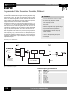
Configurable Transmitters
DSCP
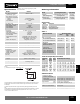
Specifications
Input Range, Thermocouple Reference Table 1
Thermocouple Types:
B,E,J,K,N,R,S,T,L,U,C,D
Cold Junction Compensation
Internal Incorporated Pt 100
External 0 to 60°C, Configurable
Input Resistance >10MΩ
Input Range, RTD Reference Table 1
RTD Types: Pt 100, Ni 100
RTD Excitation Current ≤0.20mA
Input Resistance >10MΩ
Lead Resistance ≤30Ω per Lead
Output Range 4 to 20mA or Inverse 20 to 4mA
Output Noise <1% p-p
Loop Supply Voltage 12 to 30 VDC
Reverse Supply Protection Continuous
Load Resistance See Note 1
Output Response for Input Configurable to hold value of output
Failure immediately prior to input failure, or
value between 4 and 21.6mA
Output Time Response Configurable, see Table 2
Accuracy
(2)
±0.1% Span Typ., ±0.2% Span max.
Linearity ±0.03% Span Typ., ±0.1% Span max.
Stability ≤±(0.015%+0.015°C)/°C
Environmental
Operating Temp. Range -25°C to +80°C
Storage Temp. Range -40°C to +80°C
Relative Humidity 0 to 75% Noncondensing
Emissions EN50081-2 (Radiated, Conducted)
Immunity EN50082-2 (ESD, RF, EFT)
Mechanical Dimensions 2.44 x 0.67 x 2.56
(h)(w)(d) (62mm x 17mm x 65mm)
Housing Material Polyamide, Flammability Class V2
According to UL 94
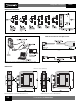
Mounting DIN EN 50022-35x7.5 or EN 50035-G32
Module DSCP20
Typical at T
A
=+25°C, 24V loop supply voltage, R
L
=250Ω;
PT100, 3 wire, 0-600°C
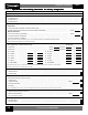
Ordering Information
Accessories
Model Input Range/Description Output Range
DSCP20 Configurable RTD or Thermocouple, 4 to 20mA,
(Basic Configuration)
(3)
User Programmed or Inverted
DSCP20-xxxx Configurable RTD or Thermocouple, 4 to 20mA,
(Contact Factory)
(4)
Factory Programmed or Inverted
DSCX-887 PC Interface Cable
DSCX-416 Module Interface Cable
DSCX-895 Configuration Software
Model Description
(2) Includes hysteresis, conformity and repeatability at reference conditions. Does not include CJC error.
(3) Shipped as PT 100 for 3-wire connection, 0 to 600°C range, 4 to 20mA output, open circuit detect =
21.6mA output.
(4) Submit configuration form shown on page 180, and factory will assign part number prior to order
entry.
(5) Many different ranges may be programmed as long as the min/max limits are observed. For minimum
range examples, a K type thermocouple could be programmed for +30°C to +78.5°C, or +100°C to
+149°C, or +900°C to 995°C, and so on.
Measured Variables Measuring Ranges
Table 1
Limits Min. Max.
Span Span
Measuring Open Short- Possible Response Times [s]
Mode Sensor Circuit
Circuit
Table 2: Output Response Times
TC int. comp. active 1.5 2.5 3.5 6.5 11 20.5 40
TC int. comp. off 1.5 2.5 3.5 6.5 13.5 24.5 49.5
TC ext. comp. active 1.5 2.5 3.5 6.5 11 20.5 40
TC ext. comp. off 1.5 2.5 4 6.5 13.5 24.5 48.5
RTD 2L active 2 2.5 3 5 9.5 17.5 33.5
RTD 3L, 4L active active 2 2.5 4 6.5 11.5 21 40.5
RTD 2L, 3L, 4L off off 1.5 2.5 3.5 7.5 14 26.5 50.5
RTD: 2, 3, or 4-wire
Pt 100, Standard IEC 60 751 -200 to +850°C 50°C 850°C
Ni 100, Standard DIN 43 760 -60 to +250°C 50°C 250°C
Thermocouple
Type B, E, J, K, N, R, S, T;
Standard IEC 60 584-1
Type L and U; According to type 2mV
(5)
80mV
(5)
Standard DIN 43 710
Type C: W5 Re/W26 Re,
Type D: W3 Re/W25 Re;
Standard ASTM E 988-90
Additional Errors
Low Measuring Range
Resistance Thermometer
(<200°C Span) ±0.015% Span Typ., ±0.05% Span max
Thermocouples (<500°C Span) ±0.015% Span Typ., ±0.05% Span max
High Initial Value Factor: ±0.0002 Typ., ±0.0005 max
Error: (Factor)*(Initial Value/Span)*100 [%]
Influence of Lead Resistance ±0.01% per Ω
Internal Cold Junction Compensation ±(0.5°C/Span)*(100) [%]
NOTES:
(1): Load Resistance: R
L
(max) = Loop Supply (V) 12V
I
OUTPUT
(max)