
Manual

Industrial Loop Isolators and Transmitters
DSCL
For information call 800-444-7644
176
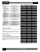
Specifications
Input Range
(1)
4-20mA
Input Limit 40mA, ±40mA(I
in
); 40V, ±40V(V
in
)
CMV Input to Output 2300Vrms, 1 min.
CMV Power Supply to I/O 3700Vrms, 1 min.
Accuracy (at 250Ω Load) ±0.1% Span Typical, ±0.2% Span Max
Input Resistance 15Ω Current Mode, 100kΩ Voltage Mode
Non-linearity Included in Accuracy
Stability <100ppm/°C
Input Overshoot <20µA (Typical 5µA)
Output Range
(1)
4-20mA
Limit Upper Range 40mA
Bandwidth, -3dB 15Hz
CMR (50Hz or 60Hz) 110dB
NMR 16dB at 50/60Hz
Response Time 30ms, to 90% Span
Load Resistance Range ≤600Ω Current Mode, ≥2kΩ Voltage Mode
Output Noise <0.5% p-p
Power Supply
Voltage (24 to 60) or (85 to 230)VDC/AC at 45-400Hz
Tolerance DC 15% to +33%, AC ±15%
Power Consumption DC ≤1.6W, AC ≤3.4VA
Environmental Weight Approximately 180g.
Housing Material Lexan 940 (UL 94 V-O)
Shock Test 50g (3 Shocks, 6 Axis)
Operating Temp Range -25°C to +55°C
Storage Temp Range -40°C to +70°C
Relative Humidity 0 to 75% Noncondensing
Emissions EN50081-2 (Radiated, Conducted)
Immunity EN50082-2 (ESD, RF, EFT)
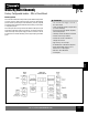
Module
DSCL24-11,-12,-21,-22
Typical at T
A
=+25°C and 24VDC or 230VAC ±10% supply voltage
NOTES:
(1) 250+ unique I/O ranges are factory configurable. See Table 1 for configuration options.
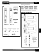
Configuration Options
The default setting of factory stock modules is 4 to 20mA for both module input
and output.
Alternatively, users may complete and submit Table 1 specifics that the factory
will use to apply solder-in jumpers configuring the module as desired.
NOTE: Modules once configured for a specific user I/O range cannot be
subsequently reconfigured.
Factory Configuration
Check-mark the desired Input and Output range for each channel in the table
at right. Copy and submit this configuration sheet with your purchase order. The
factory will assign a DSCL24-xxxx part number to your specific configuration.
This part number may be used on subsequent orders. The Span and Zero
potentiometers allow ±10% adjustments beyond the following factory solder
jumper settings.
Input Current (mA) Chn 1 Chn 2 *
0 to 0.1
0 to 0.2
0 to 0.5
0 to 1
0 to 2
0 to 5
0 to 10
0 to 20
0.2 to 1
1 to 5
2 to 10
4 to 20
-0.1 to 0.1
-0.2 to 0.2
-0.5 to 0.5
-1 to 1
-2 to 2
-5 to 5
-10 to 10
-20 to 20
Input Voltage (V) Chn 1 Chn 2 *
0 to 0.1
0 to 0.2
0 to 0.5
0 to 1
0 to 2
0 to 5
0 to 10
0 to 20
0 to 40
0.2 to 1
1 to 5
2 to 10
4 to 20
-0.1 to 0.1
-0.2 to 0.2
-0.5 to 0.5
-1 to 1
-2 to 2
-5 to 5
-10 to 10
-20 to 20
Output Current (mA) Chn 1 Chn 2
0 to 20
4 to 20
-20 to 20
Output Voltage (V) Chn 1 Chn 2
0 to 10
2 to 10
-10 to 10
* NOTE:
Inputs on Channel 2 only available on DSCL24-11 and 12
Table 1: Configuration Checklist