
User Manual


© Sealevel Systems, Inc.
- 14 -
ACB-104.ULTRA User Manual
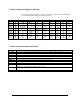
RS-485 or RS-485T
Base+5, M3-M0=4, 0100 (With termination)
Base+5, M3-M0=5, 0101 (Without termination)
Signal Name Header
Pin #
CA-118
Pin #
Mode
GND Ground 13 7
RDB RX+ Receive Positive 6 16 Input
RDA RX- Receive Negative 5 3 Input
TXCB TXC+ Transmit Clock Positive 23 12 Input
TXCA TXC- Transmit Clock Negative 4 15 Input
RXCB RXC+ Receive Clock Positive 17 9 Input
RXCA RXC- Receive Clock Negative 8 17 Input
TDB TX+ Transmit Positive 2 14 Output
TDA TX- Transmit Negative 3 2 Output
TSETB TSET+ Transmit Signal Element Timing Positive 21 11 Output
TSETA TSET- Transmit Signal Element Timing Negative 22 24 Output
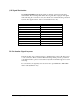
ACB-104.ULTRA shown with optional IDC26 to DB-25M 8” ribbon cable (Item# CA-118)