ACB-104.ULTRA User Manual Part Number 3514 www.sealevel.com PO Box 830 Liberty, SC 29657 864.843.
Table of Contents TABLE OF CONTENTS ............................................................................................................. 1 INTRODUCTION......................................................................................................................... 1 ACB-104.ULTRA....................................................................................................................... 1 OTHER SEALEVEL SYNC PRODUCTS ................................................................
Introduction ACB-104.ULTRA The ACB-104.ULTRA part number 3514 digital I/O interface provides 48 channels The ACB-104.ULTRA adapter provides the PC/104-Plus computer with a single channel high-speed multi-protocol serial interface suitable for the most popular communication protocols. This sync/async card provides an ideal solution for highspeed applications including LAN/WAN connectivity.
Before You Get Started What’s Included The ACB-104.ULTRA is shipped with the following items. If any of these items is missing or damaged please contact Sealevel for replacement. ACB-104.ULTRA Adapter PC/104-Plus Mounting Hardware Sealevel SeaI/O Software CD Optional Items Depending upon your application, you are likely to find one or more of the following items useful for interfacing the ACB-104.ULTRA to real-world signals. All items can be purchased from our website (http:\\www.sealevel.
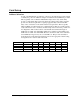
Card Setup Address Selection As part of the PC/104-Plus specification, a means of selecting the appropriate signals to identify the position in which the adapter is installed in the stack must be provided. This is typically done via Dual 4:1 Mux/Demux chips and a rotary switch. They provide a 5 ohm switch that connects the input and output together.
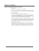
Software Installation Windows 95/98/ME/NT/2000/XP Installation 1. Start Windows. 2. Insert the Sealevel Systems CD in to your CD drive. 3. If ‘Auto-Start’ is enabled for this drive the software will automatically launch. Otherwise, point your browser to the ‘Index.htm’ on the root directory of the CD 4. Select ‘Install Software’. 5. Select the Part Number for your adapter from the listing. 6. Select ‘Windows 98/ME/2000/XP’.
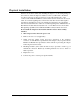
Physical Installation Extreme care should be taken when installing the adapter to avoid causing damage to the connectors. After the adapter is installed, connect your I/O cable to P1. Please note these connectors are keyed so that pin 1 of the cable matches pin 1 of the connector. The ACB-104.ULTRA is a universal bus add-in board and can be used on either 3V or 5V I/O signaling buses.
The ACB-104.ULTRA is now ready for use. © Sealevel Systems, Inc. -6- ACB-104.
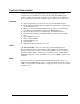
Technical Description The Sealevel Systems’ ACB-104.ULTRA adapter was designed for seamless integration into any PC/104-Plus based system. The ACB-104.ULTRA adapter requires one IRQ, an 8 byte block of I/O address and a 16K block or 256K block of memory address and additionally, the IUSC requires a 256 byte block of memory. Features Single channel high speed sync/async wide area network (WAN) interface RS-232, RS-422/449, EIA-530, V.
Status Signal LED Headers The 3514 has a pair of 2mm two-pin right angle headers at board location P6 (Tx header) and P7 (Rx header) for connecting standard off-board LEDs (headers are Hirose item# DF3-2P-2DS). Pin 1 is +5V (anode) through a 330Ω resistor and can be recognized by a square solder pad on the side of the board opposite the header. Pin 2 is the LED control (cathode), which is driven by 5V CMOS logic (74HC123) and has a round solder pad on the reverse side of the board.
Control and Status Registers Defined The control and status registers occupy 8 consecutive locations. The following tables provide a functional description of the bit positions.
Interface Selection The ACB-104.ULTRA supports a variety of electrical interfaces. Reference the Control and Status Registers Defined section of this manual for this bit description. There is line termination on RXD, RXC, and TXC in the following modes: RS-530, RS-530A, RS-485T, and V.35. Reset Circuit Writing any value to base+3 will reset the Z16C32. Only one write is required. This starts a reset sequence, which lasts about 320 ns. During the reset sequence base+3 bit D4 will read 0.
I/O Signal Derivation The ACB-104.ULTRA input/output signals are directly generated via the Zilog 16C32 IUSC. The following table defines these signals, their origin pin and signal name following the conventions set by the 16C32 user’s manual. If using a Sealevel Systems, Inc. supplied driver, this is for informational use only.
RS-232 Signals Base+5, M3-M0=2, 0010 Signal Name GND RD CTS DSR DCD RI TXC RXC TSET DTR TD RTS Ground Receive Data Clear To Send Data Set Ready Data Carrier Detect Ring Indicator Transmit Clock Receive Clock Transmit Signal Element Timing Data Terminal Ready Transmit Data Request To Send Header Pin # 13 5 9 11 15 18 4 8 22 14 3 7 CA-118 Pin # 7 3 5 6 8 22 15 17 24 20 2 4 Mode Input Input Input Input Input Input Input Output Output Output Output V.
RS-530 (RS-422) Base+5, M3-M0=D, 1101 Signal Name GND RDB RX+ RDA RXCTSB CTS+ CTSA CTSDCDB DCD+ DCDA DCDTXCB TXC+ TXCA TXCRXCB RXC+ RXCA RXCTDB TX+ TDA TXRTSB RTS+ RTSA RTSDTRB DTR+ DTRA DTRTSETB TSET+ Ground Receive Positive Receive Negative Clear To Send Positive Clear To Send Negative Data Carrier Detect Positive Data Carrier Detect Negative Transmit Clock Positive Transmit Clock Negative Receive Clock Positive Receive Clock Negative Transmit Positive Transmit Negative Request To Send Positive Request
RS-485 or RS-485T Base+5, M3-M0=4, 0100 (With termination) Base+5, M3-M0=5, 0101 (Without termination) Signal GND RDB RX+ RDA RXTXCB TXC+ TXCA TXCRXCB RXC+ RXCA RXCTDB TX+ TDA TXTSETB TSET+ TSETA TSET- Name Ground Receive Positive Receive Negative Transmit Clock Positive Transmit Clock Negative Receive Clock Positive Receive Clock Negative Transmit Positive Transmit Negative Transmit Signal Element Timing Positive Transmit Signal Element Timing Negative Header Pin # 13 6 5 23 4 17 8 2 3 21 22 CA-118 Pin
Specifications Environmental Specifications Specification Temperature Range Humidity Range Operating 0º to 70º C (32º to 158º F) 10 to 90% R.H. Non-Condensing Storage -50º to 105º C (-58º to 221º F) 10 to 90% R.H. Non-Condensing Manufacturing All Sealevel Systems Printed Circuit boards are built to UL 94V0 rating and are 100% electrically tested. These printed circuit boards are solder mask over bare copper or solder mask over tin nickel. Power Consumption Supply line Rating © Sealevel Systems, Inc.
Appendix A – Troubleshooting Following these simple steps can eliminate most common problems. Install software first. After installing the software then proceed to adding the hardware. This places the required installation files in the correct locations. Read this manual thoroughly before attempting to install the adapter in your system. Use Device Manager under Windows to verify proper installation.
Appendix B - How To Get Assistance Begin by reading through the Trouble Shooting Guide in Appendix A. If assistance is still needed please see below. When calling for technical assistance, please have your user manual and current adapter settings. If possible, please have the adapter installed in a computer ready to run diagnostics. Sealevel Systems provides an FAQ section on its web site. Please refer to this to answer many common questions. This section can be found at http://www.sealevel.com/faq.
Appendix C – Electrical Interface RS-232 Quite possibly the most widely used communication standard is RS-232. This implementation has been defined and revised several times and is often referred to as RS-232 or EIA/TIA-232. It is defined by the EIA as the Interface between Data Terminal Equipment and Data Circuit- Terminating Equipment Employing Serial Binary Data Interchange. The mechanical implementation of RS-232 is on a 25 pin D sub connector.
RS-530 / 530A RS-530 (a.k.a. EIA-530) compatibility means that RS-422 signal levels are met, and the pin-out for the DB-25 connector is specified. The EIA (Electronic Industry Association) created the RS-530 specification to detail the pin-out, and define a full set of modem control signals that can be used for regulating flow control and line status. The major difference between RS-530 and RS-530A lies in some of the modem control interface signals.
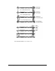
Appendix D – Silk Screen – 3514 PCB © Sealevel Systems, Inc. - 20 - ACB-104.
Appendix E - Compliance Notices Federal Communications Commission Statement FCC - This equipment has been tested and found to comply with the limits for Class A digital device, pursuant to Part 15 of the FCC Rules. These limits are designed to provide reasonable protection against harmful interference when the equipment is operated in a commercial environment.
Warranty Sealevel's commitment to providing the best I/O solutions is reflected in the Lifetime Warranty that is standard on all Sealevel manufactured products. We are able to offer this warranty due to our control of manufacturing quality and the historically high reliability of our products in the field. Sealevel products are designed and manufactured at its Liberty, South Carolina facility, allowing direct control over product development, production, burn-in and testing. Sealevel Systems, Inc.