
Manual


Card Setup
Sealevel Systems ACB-104 Page 6
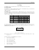
S1 Base+4 Position D7 enables DMA
S2 RTSB enables DMA
A Selects Always Enable
Note: Please refer to Section 4 for software bit definitions and examples of DMA driver control.
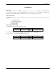
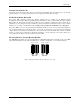
IRQ Selection Header E7
Header E7selects the interrupt request (IRQ) line for the card. If no interrupt is desired, remove the jumper.
3 4 5 7 9 10 11 12 15
Figure 6 - IRQ Header E7
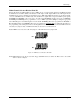
IRQ Mode Header E6
Header E6 ‘N’ indicates the (N)ormal, single interrupt mode. Position ‘M’ indicates the inclusion of a 1K ohm pull-
down resistor required on one port when sharing interrupts with another card. For shared interrupt mode, set one
board to ‘M’ and all other adapters sharing an IRQ should have neither ‘N’ or ‘M’ in place. This mode allows more
than one board to access a single IRQ.
Position ‘T’ on E6 enables the DMA Terminal Count Interrupt. Setting this jumper allows the selected DMA
channel to generate an interrupt once the DMA Terminal Count has been reached. See Section 4 for the status bit
(TC STAT) position and refer to the toolkit disk for software examples.
Note: When using multiple cards on one IRQ in shared mode, be sure that only one port has the ‘M’ jumper set,
providing the necessary pull-down resistor.
T N M
E6
Figure 7 - IRQ Mode Header