
Manual


Card Setup
Sealevel Systems ACB-104 Page 5
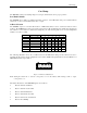
DMA Jumper Option Tables
The following tables show the jumper setting examples for each mode of DMA:
No DMA
Option E2 E3
Ch.A No DMA None None
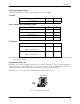
Single Channel DMA (Half Duplex Only)
Option E2 E3
DMA Channel 0 00 None
DMA Channel 1 11 None
DMA Channel 2 22 None
DMA Channel 3 33 None
Full Duplex
Option E2 E3
DMA Ch.1 Receive Data
DMA Ch.3 Transmit Data
11 33
DMA Ch.0 Receive Data
DMA Ch.2 Transmit Data
00 22
Note: DMA Channel 2 can only be used if the floppy disk DMA drivers are turned off. Please refer to the Toolkit
disk for software examples.
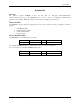
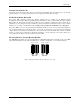
DMA Enable Header E1
Header E1 selects whether the DMA tri-state drivers are enabled permanently, (position A) disabled permanently
(jumpers removed), or which DMA enable control port bit is used to enable the DMA hardware request and
acknowledge signals. Removing the jumper disables the drivers and no DMA can be performed.
Note: The power on reset signal resets or disables the DMA software enable signal.
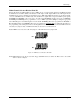
S1 S2 A
E1
Figure 5 - DMA Enable Header E1