
Manual


Card Setup
Sealevel Systems ACB-104 Page 2
Card Setup
The ACB-104 contains several jumper straps for each port, which must be set for proper operation.
Port Enable Disable
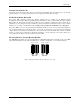
The ACB-104 can be enabled or disabled with switch position 8 on the DIP-switch. The port is enabled with the
switch ‘On’ or ‘Closed’ and disabled when ‘Off’ or ‘Open’.
Address Selection
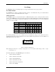
The ACB-104 occupies 8 consecutive I/O locations. A DIP-switch (SW1) is used to set the base address for these
locations. The ACB-104 can reside in any I/O location between 100 and 3F8 Hex. Be careful when selecting the
base address as some selections conflict with existing PC ports. The following table shows several examples that
usually do not cause a conflict.
Address Binary Switch Settings
A9----------A0 1 2 3 4 5 6 7
238-23F 1000111XXX Off On On On Off Off Off
280-287 1010000XXX Off On Off On On On On
2A0-2A7 1010100XXX Off On Off On Off On On
2E8-2EF 1011101XXX Off On Off Off Off On Off
300-307 1100000XXX Off Off On On On On On
328-32F 1100101XXX Off Off On On Off On Off
3E8-3EF 1111101XXX Off Off Off Off Off On Off
Figure 1 - Address Selection Table
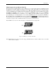
The following illustration shows the correlation between the DIP-switch setting and the address bits used to
determine the base address. In the example below, the address 300 Hex through 307 Hex is selected. 300 Hex = 11
0000 0XXX in binary representation.
1 2 3 4 5 6 7
ON
OFF
A9
A3
8
E
Figure 2 - DIP-switch Illustration
Note: Setting the switch ‘On’ or ‘Closed’ corresponds to a ‘0’ in the address, while leaving it ‘Off’ or ‘Open’
corresponds to a ‘1’.
The relative I/O address of the ACB-104 registers are as follows:
• Base+0 Channel A Data Port
• Base+1 Channel A Control Port
• Base+2 Channel B Data Port
• Base+3 Channel B Control Port
• Base+4 Board Control / Status Port
• Base+5 Reset TCIRQ