ACB-104 USER MANUAL TM Part # 3512 Sealevel Systems, Inc PO Box 830 Liberty, SC 29657 USA Phone: (864) 843-4343 FAX: (864) 843-3067 www.sealevel.
Contents INTRODUCTION ...........................................................................................................................1 OVERVIEW ................................................................................................................................................. 1 WHAT’S INCLUDED .................................................................................................................................... 1 FACTORY DEFAULT SETTINGS ................................
APPENDIX C - ELECTRICAL INTERFACE .................................................................................14 RS-232 .................................................................................................................................................... 14 RS-422 .................................................................................................................................................... 14 RS-530 .....................................................................
Introduction Introduction Overview The Sealevel Systems ACB-104 provides the PC with one high-speed RS-232/530/422/485 synchronous/asynchronous port. The ACB-104 can be used in a variety of sophisticated communications applications such as SDLC, HDLC, X.25, Bi-Sync, Mono-Sync, and high-speed asynchronous. What’s Included The ACB-104 is shipped with the following items. If any of these items are missing or damaged, contact the supplier.
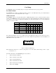
Card Setup Card Setup The ACB-104 contains several jumper straps for each port, which must be set for proper operation. Port Enable Disable The ACB-104 can be enabled or disabled with switch position 8 on the DIP-switch. The port is enabled with the switch ‘On’ or ‘Closed’ and disabled when ‘Off’ or ‘Open’. Address Selection The ACB-104 occupies 8 consecutive I/O locations. A DIP-switch (SW1) is used to set the base address for these locations.
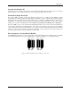
Card Setup Transmit Clock Header E5 Header E5 sets the input/output clock modes for the transmit clock (TXC). If the transmit clock is to be an input, place the jumper to cover both pins. This board does not support transmit clock as an output. RS-485 Mode Enable Header E4 E4 position ‘TE’ determines whether the RS-485 transmit driver is enabled by the Enhanced Serial Communications Controller (ESCC) signal Request To Send (RTS) or always enabled. With the jumper installed, RTS enables the driver.
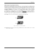
Card Setup DMA Channel Selection Headers E2 & E3 Headers E2 & E3 select Direct Memory Access (DMA) mode of operation. Each channel of the Enhanced Serial Communications Controller (ESCC) will function in half duplex or full duplex DMA modes. Full duplex means that DMA can be used for simultaneous transmit and receive. Half-duplex DMA means that you can either transmit, or receive with DMA, but not simultaneously. The 85230 has two signals that correspond to DMA request signals, WAIT/REQ and DTR/REQ.
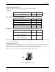
Card Setup DMA Jumper Option Tables The following tables show the jumper setting examples for each mode of DMA: No DMA Option E2 E3 Ch.A No DMA None None Option E2 E3 DMA Channel 0 00 None DMA Channel 1 11 None DMA Channel 2 22 None DMA Channel 3 33 None Option E2 E3 DMA Ch.1 Receive Data 11 33 00 22 Single Channel DMA (Half Duplex Only) Full Duplex DMA Ch.3 Transmit Data DMA Ch.0 Receive Data DMA Ch.
Card Setup S1 S2 A Base+4 Position D7 enables DMA RTSB enables DMA Selects Always Enable Note: Please refer to Section 4 for software bit definitions and examples of DMA driver control. IRQ Selection Header E7 Header E7selects the interrupt request (IRQ) line for the card. If no interrupt is desired, remove the jumper. 3 4 5 7 9 10 11 12 15 Figure 6 - IRQ Header E7 IRQ Mode Header E6 Header E6 ‘N’ indicates the (N)ormal, single interrupt mode.
Installation Installation The ACB-104 can be installed in any of the PC expansion slots The ACB-104 contains several jumper straps for each port, which must be set for proper operation. 1. 2. 3. 4. 5. Turn off PC power. Disconnect the power cord. Remove the PC case cover. Locate two available slots and remove the blank metal slot covers. Replace the cover. Connect the power cord. Installation is complete. Cabling Options The ACB-104 has a number of cabling options available.
Technical Description Technical Description The ACB-104 utilizes the Zilog 85230 Enhanced Serial Communications Controller (ESCC). This chip features programmable baud rate, data format and interrupt control, as well as DMA control. Refer to the ESCC Users Manual for details on programming the 85230 ESCC chip.
Technical Description DMA Terminal Count The ACB-104 can be setup to operate using a polling method, interrupts, or system DMA. The most efficient method is a combination of DMA and interrupts. The ACB-104 has been optimized to generate an interrupt at the end of a DMA transfer. This will allow DMA initialization and buffer management to take place at interrupt time and provide a virtually seamless communication channel.
Technical Description RS-530/422/485 Pin Assignments (At the DB-25) Signal GND RDB RDA CTSB CTSA TXCB TXCA RXCB RXCA TDB TDA RTSB RTSA DTRB DTRA TSETB TSETA RX+ RXCTS+ CTSTXC+ TXCRXC+ RXCTX+ TXRTS+ RTSDTR+ DTRTSET+ TSET- Name Ground Receive Data Positive Receive Data Negative Clear To Send Positive Clear To Send Negative Transmit Clock Positive Transmit Clock Negative Receive Clock Positive Receive Clock Negative Transmit Data Positive Transmit Data Negative Request To Send Positive Request To Send Negat
Specifications Specifications Environmental Specifications Specification Temperature Range Humidity Range Operating 0º to 50º C (32º to 122º F) 10 to 90% R.H. Non-Condensing Storage -20º to 70º C (-4º to 158º F) 10 to 90% R.H. Non-Condensing Power Consumption Supply line Rating +5 350ma Mean Time Between Failures (MTBF) Greater than 150,000 hours. (Calculated) Physical Dimensions Board length Board Height including Goldfingers Board Height excluding Goldfingers 3.75 inches 3.5 inches 3.2 inches (9.
Appendix A - Troubleshooting Appendix A - Troubleshooting An ACB Developers Toolkit Diskette is supplied with the Sealevel Systems adapter and will be used in the troubleshooting procedures. By using this diskette and following these simple steps, most common problems can be eliminated without the need to call Technical Support. 1. Identify all I/O adapters currently installed in your system. This includes your on-board serial ports, controller cards, sound cards etc.
Appendix B – Hot To Get Assistance Appendix B - How To Get Assistance Please refer to Troubleshooting Guide prior to calling Technical Support. 1. Begin by reading through the Trouble Shooting Guide in Appendix A. If assistance is still needed please see below. 2. When calling for technical assistance, please have your user manual and current adapter settings. If possible, please have the adapter installed in a computer ready to run diagnostics. 3.
Appendix C - Electrical Interface Appendix C - Electrical Interface RS-232 Quite possibly the most widely used communication standard is RS-232. This implementation has been defined and revised several times and is often referred to as RS-232 or EIA/TIA-232. It is defined by the EIA as the Interface between Data Terminal Equipment and Data Circuit- Terminating Equipment Employing Serial Binary Data Interchange. The mechanical implementation of RS-232 is on a 25 pin D sub connector.
Appendix C - Electrical Interface RS-485 RS-485 is backwardly compatible with RS-422; however, it is optimized for partyline or multi-drop applications. The output of the RS-422/485 driver is capable of being Active (enabled) or Tri-State (disabled). This capability allows multiple ports to be connected in a multi-drop bus and selectively polled. RS-485 allows cable lengths up to 4000 feet and data rates up to 10 Megabits per second. The signal levels for RS-485 are the same as those defined by RS-422.
Appendix D - Direct Memory Access Appendix D - Direct Memory Access In many instances, it is necessary to transmit and receive data at greater rates than would be possible with simple port I/O. In order to provide a means for higher rate data transfers, a special function called Direct Memory Access (DMA) was built into the original IBM PC. The DMA function allows the ACB-104 (or any other DMA compatible interface) to read or write data to or from memory without using the Microprocessor.
Appendix E - Asynchronous and Synchronous Communications Appendix E - Asynchronous and Synchronous Communications Serial data communications implies that individual bits of a character are transmitted consecutively to a receiver that assembles the bits back into a character. Data rate, error checking, handshaking, and character framing (start/stop bits or sync characters) are pre-defined and must correspond at both the transmitting and receiving ends.
Appendix E - Asynchronous and Synchronous Communications Synchronous Communications Synchronous Communications is used for applications that require higher data rates and greater error checking procedures. Character synchronization and bit duration are handled differently than asynchronous communications. Bit duration in synchronous communications is not necessarily pre-defined at both the transmitting and receiving ends. Typically, in addition to the data signal, a clock signal is provided.
Appendix F - Silk-Screen Appendix F - Silk-Screen 3.550" 3.
Warranty Warranty Sealevel Systems, Inc. provides a limited lifetime warranty. Should this product fail to be in good working order at any time during this period, Sealevel Systems will, at it’s option, replace or repair it at no additional charge except as set forth in the following terms. This warranty does not apply to products damaged by misuse, modifications, accident or disaster.