SeaDAC User Manual www.sealevel.com PO Box 830 – Liberty, SC 29657 864.843.
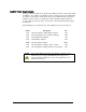
Table of Contents INTRODUCTION......................................................................................................................... 1 BEFORE YOU GET STARTED................................................................................................. 3 SEADAC HARDWARE DESCRIPTION .................................................................................. 4 SEADAC MODULE COMMON FEATURES .....................................................................................
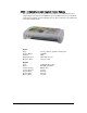
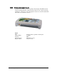
Introduction SeaDACTM modules provide a powerful way to add digital and analog I/O to a variety of computers, controllers, and PLCs. Each SeaDAC model connects to an available USB port and provides easy field wiring via removable terminal blocks. SeaDAC modules are housed in a rugged, attractive plastic enclosure and include a highretention USB type B connector to prevent accidental disconnection. SeaDAC modules are USB 1.1 compliant and USB 2.0 compatible.
Overview Sealevel SeaDAC modules are available in various I/O configurations, each designed for maximum flexibility and easy field wiring. SeaDAC modules can be used with industry standard Modbus RTU protocol or easily controlled from application programs using the supplied SeaMAX software libraries, which includes the diagnostic and configuration tool MaxSSD.
Before You Get Started What’s Included All SeaDAC modules are shipped with the following items. If any of these items is missing or damaged please contact Sealevel for a replacement. SeaDAC Digital Interface Adapter Item# CA179 – 6’ A to B USB Device Cable Sealevel SeaMAX Software CD NOTE: The SeaDAC REL-16C (Item# 8225) includes a 5VDC @ 2.4A wall-mount power supply (Item# TR101). External power is required with this module due to the power requirements of the sixteen Form C relays.
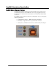
SeaDAC Hardware Description SeaDAC Module Common Features SeaDAC models include a high-retention Type B USB connector that prevents accidental disconnection of the USB cable. The orange, ruggedized connector provides up to two times the removal resistance to the cable than standard USB connectors.
SeaDAC Power Requirements Sealevel SeaDAC modules are powered by the USB host interface and require 5VDC @ 500mA to be available on the USB port. Most computers and powered USB hubs are capable of meeting this requirement, while passive USB hubs and some laptops running on batteries may not. Check the product manual that shipped with your system or hub if you are uncertain. You can also contact Sealevel technical support for assistance. The maximum power requirements for each SeaDAC device are shown below.
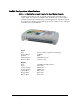
SeaDAC Configurations & Specifications 8221 – 16 Optically Isolated Inputs/16 Reed Relay Outputs SeaDAC 8221 modules provide 16 optically isolated inputs and 16 Reed relay outputs. Inputs can range from 5-30VDC, while the Reed relays provide long life switch closures that are well suited for low current applications. Inputs and outputs are grouped into four-bit segments. Each group shares a common for easy wiring via removable 3.5mm terminal blocks.
8222 – 16 Optically Isolated Inputs/8 Form C Outputs The SeaDAC 8222 provides 16 optically isolated inputs and 8 SPDT Form C relay outputs. Inputs can range from 5-30VDC and provide 300V isolation to ground. Each output offers normally open and normally closed contact connections via 3.5mm field removable terminal blocks. Inputs Type: Voltage Range: Isolation: Input Resistance: Response Time: 16 non-polarized optically isolated inputs 5-30VDC 300V 6.
8223 – 32 Optically Isolated Inputs SeaDAC 8223 modules provide 32 optically isolated inputs with 300V external isolation and high channel-to-channel isolation. Ideal for low voltage monitoring applications, connection to real world signals is made via convenient 3.5mm field removable screw terminal connectors. Inputs Type: Voltage Range: Isolation: Input Resistance: Response Time: © Sealevel Systems, Inc. 32 non-polarized optically isolated inputs 5-30VDC 300V 6.
8224 – 32 Reed Relay Outputs The SeaDAC 8224 provides 32 SPST Form A dry-contact Reed relays. Reed relays offer long life performance and fast response time. Convenient removable 3.5mm screw terminal blocks compatible with 14-22 AWG wiring allow reliable connection to real world I/O. Outputs Type: Power: Contact Voltage: Contact Current: Operate Time: Bounce Time: Release Time: © Sealevel Systems, Inc. 32 SPST Form A Reed relays 10VA max. 60VDC max. 500mA max. 0.5ms max. 0.5ms max. 0.2ms max.
8225 – 16 Form C Relay Outputs Control a variety of low voltage, low current devices with the SeaDAC 8225. The module’s 16 channels of highly reliable SPDT Form C relay outputs are rated for up to 60VDC @ 2A. Each output offers normally-open and normally-closed contact connections via 3.5mm field removable terminal blocks. Outputs Type: Power: Contact Voltage: Contact Current: Operate Time: Bounce Time: Release Time: © Sealevel Systems, Inc. 16 SPDT Form C relays DC 30W/ AC 60 VA 60VDC max. 2A max.
8227 – 16 A/D, 2 D/A, 8 24V Outputs, 8 Isolated Inputs Designed using the Maxim MAX197 successive approximation-type A/D chip, the SeaDAC 8227 provides eight differential or 16 single-ended 12-bit inputs. The A/D inputs can be individually configured for sensing 4-20mA current loop signals. Additionally, the module provides two 12-bit D/A output channels, eight optically isolated inputs, and eight open collector outputs, ideal for driving 24V devices commonly found in industrial environments.
8232 – 8 Optically Isolated Inputs/8 High-Current Form C Outputs The SeaDAC 8232 provides 8 optically isolated inputs and 8 SPDT high-current Form C relay outputs. Inputs can range from 5-30VDC and provide 300V isolation to ground. Each output offers normally open and normally closed contact connections via 3.5mm field removable terminal blocks. Inputs Type: Voltage Range: Isolation: Input Resistance: Response Time: 8 non-polarized optically isolated inputs 5-30VDC 300V 6.
SeaMAX Application Suite SeaMAX Overview The SeaMAX Suite is a collection of software libraries, and configuration and diagnostic utilities that facilitates rapid application development for SeaI/O, SeaDAC, and SeaDAC Lite modules.
Communicating Via Modbus Sealevel SeaI/O and SeaDAC modules are designed to integrate seamlessly into existing Modbus networks. The supported command set will vary depending on the SeaI/O model number used. Specialized diagnostic commands and other RTU specific codes are not supported. An overview of the Modbus specification for both RTU and TCP connections is covered in detail in the interactive documentation located on the Sealevel website at: http://www.sealevel.
SeaMAX Software Installation Proceed with installing the SeaMAX Software Suite using the software CD that was included with your Sealevel I/O module. Software drivers are also available on the product webpage on the Sealevel website at www.sealevel.com. Windows 2000/XP/Vista™ Operating Systems Do not connect the I/O module to the host until the software is installed. 1. Start Windows. 2. Insert the Sealevel Software CD in to your CD drive. 3.
MaxSSD Configuration & Diagnostics Utility The Sealevel Systems configuration utility, MaxSSD, is designed to simplify the installation, configuration, and diagnostics of Sealevel I/O modules. MaxSSD is a Microsoft Windows application and has been tested with Windows 2000, XP, and Vista. Host PC Configuration Tab The first time you run the MaxSSD utility (Start Æ All Programs Æ Sealevel SeaMAX Æ MaxSSD) it will default to the “Host PC Configuration” tab.
Host PC Configuration Tab (cont.) To communicate with a SeaDAC Lite module, select “SeaDAC Lite” from the “COM Port” dropdown box. MAXSSD will search for any SeaDAC Lite modules connected to a USB port and display them in a frame (as shown below). A new “Digital I/O” tab will appear. If more than one SeaDAC Lite module is connected, select the one you want to test from the list and click the “Digital I/O tab”. You can use this new tab to test the functionality of inputs and relay outputs.
SeaI/O Configuration Tab Once the host computer is configured correctly, the “SeaI/O Configuration” tab becomes available. This tab only appears for SeaI/O and SeaDAC modules and will not appear when using SeaDAC Lite modules. Before communicating with a SeaI/O or SeaDAC module, the configuration utility must determine if there is an I/O module at that slave ID address, and if so, what type of module it is. This is the purpose of the Get operation.
SeaI/O Configuration Tab (cont.) After the Get command is executed, the “Module Description” frame will display the model type, description, interface, and I/O type. In the example shown, the module found at slave ID 247 is a SeaI/O-410 module with an Ethernet (Modbus TCP) interface. The “Set Settings” and “Change Slave ID” buttons will also be enabled for this module. After a successful Get operation, additional tabs may be displayed in MaxSSD, depending on the found device model.
SeaI/O Configuration Tab (cont.) The “Broadcast to Multiple Modules” checkbox, along with the “Set Settings” button can be used to change the baud rate and parity on multiple SeaI/O modules at once. This function only works with SeaI/O modules connected together via the passthrough connectors. This function is disabled with SeaDAC and SeaDAC Lite modules since these devices do not have pass-through connectors.
Digital I/O Tab The “Digital IO” tab of MaxSSD is displayed when using Sealevel I/O devices featuring discrete inputs and outputs. It displays the device’s current input and/or output status in an intuitive and usable manner. When displaying SeaI/O or SeaDAC modules (excluding SeaDAC Lite), the “Digital IO” tab displays inputs and outputs in groupings (or banks) of eight. Therefore, a Sealevel I/O device with 16 inputs and 8 outputs would show two banks of inputs and one bank of outputs.
Digital I/O Tab (cont.) When displaying SeaDAC Lite modules, the “Digital IO” tab displays inputs and outputs in groupings (or banks) of four. Therefore, a SeaDAC Lite module with four inputs and four outputs would show only one bank of inputs and one bank of outputs. When banks of inputs are displayed, the status LEDs update on each of the banks automatically. This allows you to actively monitor external signals. With a bank of outputs, the output coils can be set using the buttons below each output LED.
Programmable I/O Tab The “Programmable IO” tab of MaxSSD is displayed when using Sealevel I/O devices featuring programmable inputs or outputs. This tab allows for bank configuration, input/output configuration, as well as bit-level presets. Each bank of programmable I/O can be set as either an 8-bit group of inputs or outputs.
A/D Inputs Tab The “A/D Inputs” tab displays the current state of the analog-to-digital channels for Sealevel I/O devices that feature A/D inputs. Settings are provided for both device wide and per-channel configuration. The “Device Configuration” selection drop-box adjusts the arrangement and function of the A/D input channels. Input channels are displayed as banks (groups of eight). Each channel is range configurable via the voltage range dropdown list.
D/A Outputs Tab The “D/A Outputs” tab is useful for manually setting the digital to analog output voltages on applicable Sealevel I/O devices with D/A channels. A preliminary diagnostics utility (see following page) has been provided to verify proper hardware functionality. The D/A outputs of the SeaI/O-470 and SeaDAC 8227 are factory set for 0-10V. To configure the D/A outputs for 0-5V, you will need to open the enclosure and set the correct jumpers.
A/D & D/A Diagnostics To check basic functionality of both the A/D and D/A converters, press the “Diagnostics Utility” button on the “D/A Outputs” tab (shown on the previous page) and then press the “Start” button, as shown below. Any errors will be shown in the “Results” pane. If any errors occur, please contact technical support for further help.
Troubleshooting SeaMAX Following these simple steps can eliminate most common problems. 1. Read this manual thoroughly before attempting to install the device in your system. 2. Uninstall any previous versions of the SeaMAX software before installing any new versions. 3. Install SeaMAX software first, before connecting any Sealevel I/O devices. Installing the software places the necessary files in the proper locations on your system. After installing the software, proceed with adding the hardware. 4.
Troubleshooting Ethernet (E-series) SeaI/O Modules Problem: The SeaI/O module starts up with a strange IP address (i.e., 169.254.x.x) All Ethernet SeaI/O (E-series) modules are shipped with DHCP enabled. If no DHCP server is available or the DHCP server cannot be reached, the Ethernet SeaI/O module will default to a random IP address in the range 169.254.0.1 to 169.254.255.254. Change the PC’s network settings to place both the SeaI/O module and PC on the same subnet.
Hardware Configuration 8227 – Jumper and Dipswitch Settings The SeaDAC 8227 module ships factory configured with the D/A outputs set for 010V and current loop mode on the A/D inputs disabled. If you need to enable current loop mode or set the D/A outputs to 0-5V, you will need to open the enclosure and access the jumpers (shown on the next page). NOTE: Do not perform these instructions with USB or field wires connected. Be sure to follow proper ESD procedures by grounding yourself and the SeaDAC module.
SeaDAC 8227 Jumper Locations This detail image of the right side of the SeaDAC 8227 circuit board shows the locations of the user configurable jumpers and dipswitches. Refer to the following pages for instructions on properly configuring the jumpers and switches. The colored boxes are shown here for clarity and are not visible on the actual circuit board. © Sealevel Systems, Inc.
D/A Settings The (E1) and (E2) jumpers (shown in the orange boxes on the previous page) configure the D/A outputs for 0-5V or 0-10V. Both channels can be configured independently. The D/A outputs do not support negative voltages. You must also set the correct output voltage in your application or MaxSSD. Refer to the SeaMAX Application Suite section of this manual for help configuring software to work with the SeaDAC 8227.
Wiring Options I/O Wiring – SeaDAC 8221, 8222, 8223, 8224, and 8225 Modules Optically isolated inputs are arranged such that each group of four shares a single common. The four I/O points and shared common are connected via a five-position removable screw terminal. Input voltage range is 5-30VDC. Like the inputs, each group of four Reed relays also shares a single common and connects via a fiveposition removable screw terminal.
I/O Wiring – SeaDAC 8227 Modules A/D Wiring Connections The SeaDAC 8227 supports single-ended, differential, and current loop A/D inputs. Single-ended and differential modes can be configured in software. Current loop mode requires configuring dipswitches inside the enclosure. Refer to the Hardware Configuration section of this manual for instructions on configuring the current loop dipswitches. The SeaDAC 8227 can be configured for up to sixteen 12-bit single-ended A/D inputs.
The SeaDAC 8227’s A/D channels can also be configured to provide up to eight 12bit current loop inputs. Each input has two terminals – one positive and one negative. The input current range is 0-20mA for interfacing commonly used 4-20mA devices. The dipswitches inside the enclosure must be properly configured for each current loop input. D/A Wiring Connections The SeaDAC 8227 provides two 12-bit D/A output channels, configured for 0-10V. 0-5V mode requires different jumper settings inside the enclosure.
Digital I/O Wiring Connections The SeaDAC 8227 modules include eight optically isolated inputs that are arranged such that each group of four inputs shares a single common. The four I/O points and shared common are connected via a five-position removable screw terminal. The SeaDAC 8227 modules provide eight open-collector digital outputs. The outputs do not source any current and must be connected to an external power source, max 30VDC. The outputs act as a switch and the circuit is open until energized.
I/O Wiring – SeaDAC 8232 Modules Optically isolated inputs are arranged such that each group of two shares a single common. The four I/O points and shared common are connected via a six-position removable screw terminal. Input voltage range is 5-30VDC. Like the inputs, each group of two Form C relays also shares a single common. The NC and NO contacts of each relay along with the commons are brought out via a six-position removable screw terminal. © Sealevel Systems, Inc.
Appendix A – How to Get Assistance When calling for technical assistance, please have your user manual and current device settings ready. If possible, please have the device installed and ready to run diagnostics. Sealevel Systems maintains a website on the Internet. Our homepage address is http://www.sealevel.com. The latest software updates and newest manuals are available via our FTP site that can be accessed from our home page.
Appendix B – Compliance Notices Federal Communications Commission Statement FCC - This equipment has been tested and found to comply with the limits for Class A digital device, pursuant to Part 15 of the FCC Rules. These limits are designed to provide reasonable protection against harmful interference when the equipment is operated in a commercial environment.
Warranty Sealevel's commitment to providing the best I/O solutions is reflected in the Lifetime Warranty that is standard on all Sealevel manufactured products. We are able to offer this warranty due to our control of manufacturing quality and the historically high reliability of our products in the field. Sealevel products are designed and manufactured at its Liberty, South Carolina facility, allowing direct control over product development, production, burn-in and testing. Sealevel Systems, Inc.