PIO-24.LPCI User Manual Part Number 8018 www.sealevel.com PO Box 830 Liberty, SC 29657 864.843.
Table of Contents INTRODUCTION....................................................................................................................................... 1 OTHER SEALEVEL PCI DIGITAL I/O PRODUCTS ....................................................................................... 1 BEFORE YOU GET STARTED ............................................................................................................... 2 WHAT’S INCLUDED .............................................................
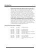
Introduction The PIO-24.LPCI, part number 8018, digital I/O interface provides 24 channels of buffered drive digital I/O emulating 8255 mode zero. The PIO-24.LPCI can be utilized for a variety of control and automation applications including control and monitoring of TTL devices (e.g. LEDs, small solenoids, small relays) and interfacing to solid-state relay racks (SSRs) for high-power AC or DC loads. The PIO-24.
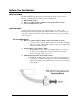
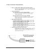
Before You Get Started What’s Included The PIO-24.LPCI is shipped with the following items. If any of these items is missing or damaged please contact Sealevel for replacement. PIO-24.LPCI Adapter IDC 50 to (2) IDC 26 Pin 40" Ribbon Cable (Part Number CA315) Sealevel SeaI/O Software CD Optional Items Depending upon your application, you are likely to find one or more of the following items useful for interfacing the PIO-24.LPCI to real-world signals.
For high-current, high-voltage applications: IDC 50 to (2) IDC 26 Pin 40" Ribbon Cable (Part Number CA315) − Connects to the two 26-pin header connectors on the 8018 and brings them out to a single 50-pin IDC connector, which is compatible with industry-standard relay racks. Solid-State Relay Racks: • Quad six position relay rack (Part Number PB24HQ) − Relay rack can accept up to six QSSRs for a total of 24 channels.
Software Installation Windows 98/ME/2000/XP Installation 1. Start Windows. 2. Insert the Sealevel Systems CD in to your CD drive. 3. If ‘Auto-Start’ is enabled for this drive the software will automatically launch. Otherwise, point your browser to the ‘Index.htm’ on the root directory of the CD 4. Select ‘Install Software’. 5. Select the Part Number for your adapter from the listing. 6. Select ‘Windows 98/ME/2000/XP’.
Linux Installation Note: You MUST have "root" privileges to install the software and drivers. 1. Login as "root". 2. Mount the CDROM by typing: mount -t iso4860 /dev/hdc /cdrom Note Your cdrom may not be /dev/hdc it could be /dev/hda, /dev/hdb, /dev/hdd, or if you have a SCSI drive /dev/sda, /dev/sdb, /dev/sdc, etc. You may mount the CDROM to any location, the /cdrom is just a common example. 3. Next change to the directory where you mounted the CDROM: Ex.
Physical Installation The adapter can be installed in any 3.3V or 5V Low Profile or PCI expansion slot. Do not install the Adapter in the machine until the software has been fully installed. 1. Turn off PC power. Disconnect the power cord. 2. Remove the PC case cover. 3. Locate an available Low Profile or PCI slot and remove the blank metal slot cover. 4. Carefully route the CA315 cable thru the opening in the bracket. Connect each header to the card and secure the strain relief 5.
Digital I/O Interface The PIO-24.LPCI’s 24 digital I/O channels are accessed via two (2) 26-pin header connectors. The included CA315 connects to the two 26-pin header connectors on the PIO-24.LPCI and brings them out to a single 50-pin IDC connector, which is compatible with industry-standard relay racks. The headers provide 24 bits of digital I/O divided into three eight-bit ports. Each port may be individually configured via software command as input or output.
Reading the Inputs The inputs are active true. If an input is driven high (2V to 5.25 V) it will read as a logical one, if driven low (0V to 0.8V) it will read as a logical zero. If an input is not driven it will read as a one due to the 10K ohm pull up resistors on each port. Reading the Outputs The value that is currently being used to drive the outputs will be returned. © Sealevel Systems, Inc. -8- PIO-24.
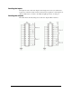
CA315 50-Pin IDC Connector – Pin Out © Sealevel Systems, Inc. -9- PIO-24.
Programming the PIO-24.LPCI Presetting an Output Port Each port has an output register associated with it. This register may be written and retains its value whether the port is configured as an input or an output. To preset the value of an output port the program should write to the port when it is configured as an input then configure it as an output. Writing the Outputs The outputs are active true. Writing a one (1) corresponds to 5V while writing a zero (0) corresponds to 0V, at the output.
I/O Control Word Each port may be configured as either Input or Output. This is accomplished by writing the correct Control Word (CW) to the proper register.
Electrical Characteristics The PIO-24.LPCI uses 74LS245 octal bi-directional transceivers to provide TTL input/output capabilities. Each bit is pulled to +5V through a 10K ohm pull-up resistor to insure each bit is at a known state when not driven. Specifications Inputs Logic High: Logic Low: Min 2VDC Max 0.8VDC Outputs Logic High: Logic Low: Min 2VDC @ 15 mA Max 0.
Example Circuits © Sealevel Systems, Inc. - 13 - PIO-24.
Appendix A - Troubleshooting Following these simple steps can eliminate most common problems. 1. Install software first. After installing the software then proceed to adding the hardware. This places the required installation files in the correct locations. 2. Read this manual thoroughly before attempting to install the adapter in your system. 3. Use Device Manager under Windows to verify proper installation. 4.
Appendix B - How To Get Assistance Begin by reading through the Trouble Shooting Guide in Appendix A. If assistance is still needed please see below. When calling for technical assistance, please have your user manual and current adapter settings. If possible, please have the adapter installed in a computer ready to run diagnostics. Sealevel Systems provides an FAQ section on its web site. Please refer to this to answer many common questions. This section can be found at http://www.sealevel.com/faq.
Appendix C – Silk Screen – 8018 PCB © Sealevel Systems, Inc. - 16 - PIO-24.
Appendix D - Compliance Notices Federal Communications Commission Statement FCC - This equipment has been tested and found to comply with the limits for Class A digital device, pursuant to Part 15 of the FCC Rules. These limits are designed to provide reasonable protection against harmful interference when the equipment is operated in a commercial environment.
Warranty Sealevel's commitment to providing the best I/O solutions is reflected in the Lifetime Warranty that is standard on all Sealevel manufactured products. We are able to offer this warranty due to our control of manufacturing quality and the historically high reliability of our products in the field. Sealevel products are designed and manufactured at its Liberty, South Carolina facility, allowing direct control over product development, production, burn-in and testing. Sealevel Systems, Inc.