
Manual


© Sealevel Systems, Inc.
- 10 -
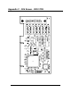
DIO-16.LPCI User Manual
Register Description
All ports are set to input after reset or power up.
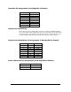
Address Mode D7 D6 D5 D4 D3 D2 D1 D0
Base+0
Input Port A RD PAD7 PAD6 PAD5 PAD4 PAD3 PAD2 PAD1 PAD0
Base+2
Output Port C RD/WR PCD7 PCD6 PCD5 PCD4 PCD3 PCD2 PCD1 PCD0
Base+5
Interrupt Status RD/WR IRQEN IRQST 0 0 0 0 IRC1 IRC0
Interrupt Control
When enabled, interrupts are generated on Port A bit D0.
IRQEN
Interrupt enable 1 = enabled 0 = disabled ( 0 on power up )
IRC0
IRC1
Interrupt mode select, see table below
Interrupt mode select, see table below
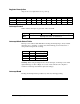
Interrupt Mode Select Table
Interrupt source is Base+0 bit D0. When selecting the Interrupt Type, always disable
interrupts prior to changing or setting states. This will help prevent inadvertent or
unexpected interrupts from occurring.
IRC1 IRC0 Interrupt Type
0 0 Low Level
0 1 High Level
1 0 Falling Edge
1 1 Rising Edge
Warning: When using the High and Low Level interrupts, an interrupt occurs when
input D0 changes to either a High or Low state. This will cause the computer to
remain in an interrupt state until the input state changes.
Interrupt Read
Reading the Interrupt Status port (Base+5) clears any interrupt pending.
IRQST (D0) Interrupt Status 1 = interrupt pending, 0 = none