DIO-32.PCIe User Manual Part Number 8004e www.sealevel.com PO Box 830 Liberty, SC 29657 864.843.
Table of Contents INTRODUCTION......................................................................................................................... 1 BEFORE YOU GET STARTED ................................................................................................. 2 WHAT’S INCLUDED ...................................................................................................................... 2 OPTIONAL ITEMS....................................................................................
Introduction The DIO-32.PCIe digital I/O interface provides 16 optically isolated inputs and 16 reed relay outputs. The inputs protect the PC and other sensitive equipment from spikes and ground loop current that can be generated in industrial environments, while the outputs provide high quality, long life, low current (10 Watt maximum), dry contact switch closures. Reed relays are well suited for low current applications. The relays are normally open, and close when energized.
Before You Get Started What’s Included The DIO-32.PCIe is shipped with the following items. If any of these items is missing or damaged please contact Sealevel for replacement. Item# 8004e – DIO-32.
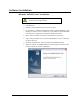
Software Installation Windows 2000/XP/Vista™ Installation Do not install the PCI Express board until the software has been successfully installed. 1. Start Windows. 2. Insert the Sealevel Software CD in to your CD drive. 3. If ‘Auto-Start’ is enabled, the installation window will automatically appear. Otherwise, navigate to the root directory of your CD drive and double-click the ‘autorun.exe’ application to launch the installation window. 4.
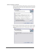
Software Installation, continued 8. When the ‘License Agreement’ window appears, accept the terms and click ‘Next’ to continue. You can click the ‘Print’ button to print out a copy of the agreement for your records. If you do not accept the terms of the agreement, the installation will stop. 9. When the ‘Ready to Install the Program’ window appears, click the ‘Install’ button to install the software onto the hard drive of your computer.
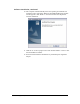
Software Installation, continued 10. The setup file will automatically detect the operating environment and install the proper components. When the ‘InstallShield Wizard Complete’ window appears, click ‘Finish’ to close the window and complete the software installation. 11. Click the ‘X’ in the top-right corner of the ‘Product Finder’ screen to close the CD installation window. 12. Proceed with the hardware installation of your PCI Express digital I/O adapter. © Sealevel Systems, Inc. -5- DIO-32.
Linux Installation Licensing Information This package contains two components - a Linux kernel-mode device driver and an Application Programmer's Interface. To provide the most flexible licensing scheme, the driver is released under the GNU General Public License version 3 while the API is released under the GNU Lesser General Public License, also version 3. Copies of each license are located in the dox/ directory.
Optional make commands: "make" or "make subdirs": this option will build all binaries, but will not copy them to the locations described below. "make objs": this option is similar to "make subdirs", but instead of building executables, only objects will be created. "make clean": this option removes all the build/executable files in the working SeaIo directory. Installed files remain on your system. "make uninstall": this option removes files that were previously installed to the locations described below.
Installation Steps Note: You MUST have "root" privileges to install the software and drivers. 1. Login as "root". 2. Mount the CDROM by typing: mount -t iso4860 /dev/hdc /cdrom Note Your cdrom may not be /dev/hdc it could be /dev/hda, /dev/hdb, /dev/hdd, or if you have a SCSI drive /dev/sda, /dev/sdb, /dev/sdc, etc. You may mount the CDROM to any location, the /cdrom is just a common example. 3. Next change to the directory where you mounted the CDROM: Ex.
Hardware Installation Do not install the PCI Express board until the software has been successfully installed. The DIO-32.PCIe does not need to be configured prior to installation. Once you have installed the SeaI/O Classic software, install the board into an available PCI Express slot and boot the computer. The Found New Hardware wizard will appear. The drivers that were installed during the software installation process will automatically be used to configure the adapter.
Hardware Installation, continued 4. The appropriate drivers for your digital I/O device and version of Windows will be installed as shown. 5. Click ‘Finish’ to complete the installation of your hardware. 6. When the ‘Found New Hardware’ alert informs you that your hardware is installed and ready to use, you can proceed with verifying the installation to check functionality if necessary. © Sealevel Systems, Inc. - 10 - DIO-32.
Verifying Installation To confirm that the digital I/O card has been successfully installed and recognized by your operating system, look in the Windows Device Manager. To access Device Manager, follow the steps below: 1. Right click on ‘My Computer’ icon on your desktop or in the Start menu. 2. Click ‘Manage’ in the fly out menu to launch the ‘Computer Management’ console window. 3. In the left pane under ‘System Tools’, click ‘Device Manager’. 4.
Programming the DIO-32.PCI Sealevel’s SeaI/O Classic software is provided to assist in the development of reliable applications for the Sealevel Systems family of PCI and PCI Express digital I/O adapters. The SeaI/O Classic software is included on the CD that shipped with the board. The software contains driver functions for use in accessing the I/O as well as helpful samples and utilities.
Input Ports Ports A and B are 8 bit input ports connected to optically isolated input sensors. Each sensor can be used to interface a voltage input and then sense whether the voltage is on or off. Each sensor is isolated (with respect to a common ground) from every other sensor, and also isolated with respect to the host PC ground.
Input Ports Pin Assignments (DB-37 Female) Inputs are interfaced via the DB-37 female connector on the supplied CA165 cable. Port A Bit 0 1 2 3 4 5 6 7 Ground +12 Volts +5 Volts NOTE: Port A Pins 18,37 17,36 16,35 15,34 14,33 13,32 12,31 11,30 2,20,21 1 19 Port B Bit 0 1 2 3 4 5 6 7 Port B Pins 10,29 9, 28 8,27 7,26 6,25 5,24 4,23 3,22 The CA165 cable input pin out is not compatible with the 3093 ISA digital I/O board.
DB-78 Female Pin Assignments (Card Edge Connector) Bit 0 1 2 3 4 5 6 7 GND +12V +5V Port A Pins Port B Pins 55,74 47,66 54,73 46,65 53,72 45,64 52,71 44,63 51,70 43,62 50,69 42,61 49,68 41,60 48,67 40,59 39,57,58 38 56 Port C Pins Port D Pins 2,20 10,28 3,21 11,29 4,22 12,30 5,23 13,31 6,24 14,32 7,25 15,33 8,26 16,34 9,27 17,35 18,36,37 1 19 Direct Hardware Control In systems where the users program has direct access to the hardware (DOS) the tables that follow give the mapping and functions that the DI
Register Description All ports are set to input after reset or power up. Address Base+0 Base+1 Base+2 Base+3 Base+4 Mode Input Port A RD Input Port B RD Output Port C RD/WR Output Port D RD/WR RD © Sealevel Systems, Inc. D7 PAD7 PBD7 PCD7 PDD7 0 D6 PAD6 PBD6 PCD6 PDD6 0 D5 PAD5 PBD5 PCD5 PDD5 0 - 16 - D4 PAD4 PBD4 PCD4 PDD4 0 D3 PAD3 PBD3 PCD3 PDD3 0 D2 PAD2 PBD2 PCD2 PDD2 0 D1 PAD1 PBD1 PCD1 PDD1 0 DIO-32.
Optional 3093 Migration Cable (CA378) On the 3093 ISA digital I/O board, the input pins #1 and #19 are reversed from the standard CA165 cable that ships standard with the 8004. If you are upgrading from a 3093 ISA board to an 8004 PCI board and wish to preserve existing infrastructure wiring, order the CA378 cable and use it in place of the standard CA165 cable. CA378 Input Pin Assignments (DB-37 Female) Inputs are interfaced via the DB-37 female connector on the optional CA378 cable.
Electrical Characteristics Features 2 sets SPST relays with each having 8 relays 2 eight bit input ports DB-37 Male connector for relay outputs DB-37 Female connector for optically isolated inputs Highly reliable 10 VA DIP reed relays Multiple adapters can reside in same computer Specifications Input Ports Turn On Current: Isolator Diode Drop: Resistor Power Max: Maximum Input Range: Maximum Input Current: 3mA 1.1 VDC .
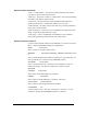
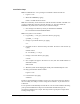
Example Circuits Input Circuit Output Circuit © Sealevel Systems, Inc. - 19 - DIO-32.
Appendix A - Troubleshooting Following these simple steps can eliminate most common problems. 1. Install software first. After installing the software then proceed to adding the hardware. This places the required installation files in the correct locations. 2. Read this manual thoroughly before attempting to install the adapter in your system. 3. Use Device Manager under Windows to verify proper installation. Refer to the Verifying Hardware section of this manual for instructions. 4.
6. VBTest is another utility included with SeaI/O Classic software. The source code is included to aid with Visual Basic application development. © Sealevel Systems, Inc. - 21 - DIO-32.
7. SeaIOTST is a command line utility that allows you to test the function calls from the SeaI/O Classic API. Notes: The source code for all utilities is located in the following folder: C:\Program Files\SeaIO\Samples The API is documented in the SeaIO help file. Start Æ All Programs Æ SeaIO Æ SeaIO Help. Launch the help file and expand the Programmers Interface section. If these steps do not solve your problem, please call Sealevel Systems’ Technical Support, (864) 843-4343.
Appendix B - How To Get Assistance Begin by reading through the Trouble Shooting Guide in Appendix A. If assistance is still needed please see below. When calling for technical assistance, please have your user manual and current adapter settings. If possible, please have the adapter installed in a computer ready to run diagnostics. Sealevel Systems provides an FAQ section on its web site. Please refer to this to answer many common questions. This section can be found at http://www.sealevel.com/faq.
Appendix C – Silk Screen – 8004e PCB © Sealevel Systems, Inc. - 24 - DIO-32.
Appendix D - Compliance Notices Federal Communications Commission Statement FCC - This equipment has been tested and found to comply with the limits for Class A digital device, pursuant to Part 15 of the FCC Rules. These limits are designed to provide reasonable protection against harmful interference when the equipment is operated in a commercial environment.
Warranty Sealevel's commitment to providing the best I/O solutions is reflected in the Lifetime Warranty that is standard on all Sealevel manufactured products. We are able to offer this warranty due to our control of manufacturing quality and the historically high reliability of our products in the field. Sealevel products are designed and manufactured at its Liberty, South Carolina facility, allowing direct control over product development, production, burn-in and testing. Sealevel Systems, Inc.