
Manual


Technical Description
Sealevel Systems VERSA COMM+4.LPCI Page 6
Technical Description
The VERSA COMM+4.LPCI utilizes the 16C854 UART. This chip features programmable baud rate, data format,
interrupt control and a 128-byte input and output FIFO, and is functionally 4 16C850 UARTs.
Connector Pin Assignments
DB-25 Female (RS-232 DTE)
Signal Name Pin # Mode
GND Ground 7
TD Transmit Data 2 Output
RTS Request To Send 4 Output
DTR Data Terminal Ready 20 Output
RD Receive Data 3 Input
CTS Clear To Send 5 Input
DSR Data Set Ready 6 Input
DCD Data Carrier Detect 8 Input
RI Ring Indicator 22 Input
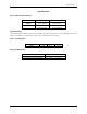
DB-9 Male (EIA-574 DTE)
Signal Name Pin # Mode
GND Ground 5
TD Transmit Data 3 Output
RTS Request To Send 7 Output
DTR Data Terminal Ready 4 Output
RD Receive Data 2 Input
CTS Clear To Send 8 Input
DSR Data Set Ready 6 Input
DCD Data Carrier Detect 1 Input
RI Ring Indicator 9 Input
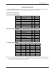
Card Edge DB-44 Female
Port # 1 2 3 4
GND 17 21 24 28
RD 4 8 12 30
RI 33 37 41 44
DCD 3 7 11 15
DTR 32 36 40 43
RTS 2 6 10 14
DSR 31 35 39 42
TD 1 5 9 13
CTS 16 20 23 27
Note: Please terminate any control signals that are not going to be used. The most common way to do this is connect
RTS to CTS and RI. Also, connect DCD to DTR and DSR. Terminating these pins, if not used, will help
insure you get the best performance from your adapter.