
Manual


Electrical Interface Modes
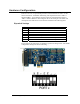
Each port on the 7205e can be individually configured for RS-232, RS-422, or RS-
485 mode. The first two switches labeled ‘M1’ and ‘M0’ are used to select the
electrical interface. To simplify installation and testing the board is shipped in RS-
422 mode. Use the settings in the table below to assist you in configuring the
electrical interface.
M1 M0 Interface
OFF OFF RS-232
OFF ON RS-422 [Default]
ON OFF RS-485 ECHO Enabled
ON ON RS-485 No ECHO
Termination & Biasing Resistors
Typically, each end of the RS-485 bus must have line terminating resistors enabled
(RS-422 should terminate the receive end only). A 120 ohm resistor is across each
RS-422/485 input in addition to a 1K ohm pull-up and pull-down combination that
biases the receiver inputs. Use the switches detailed in the table below to customize
the interface to your specific requirements.
If using the board in an RS-485 two-wire network, enable the two switches labeled
‘L’, which tie the positive/negative transmit/receive pairs together.
Switch Default Description
T ON Adds 120Ω termination, OFF to remove
PU ON Adds 1K Ω pull-up resistor in RS-422/485
Off to remove
PD ON Adds 1K Ω pull-down resistor in RS-422/485
OFF to remove
L OFF ON to connect TX– to RX– for RS-485 two-wire
L OFF ON to connect TX+ to RX+ for RS-485 two-wire
© Sealevel Systems, Inc.
- 4 -
COMM+2.LPCIe User Manual