
Manual


Cable Pin Assignments
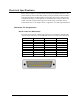
The 7205e includes a cable (Item# CA203) with a DB25 female connector
terminating to a pair of DB9 male connectors. The DB25F connector on the cable
plugs into the DB25M connector on interface board. The DB9M connectors are
compatible with a variety of serial peripherals. The pin assignments for the
supported electrical interfaces are shown in the
tables below.
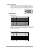
RS-232 (DB9 Male)
These RS-232 pin assignments meet EIA/TIA/ANSI-574 DTE specifications for
DB9 type connectors.
Pin # Signal Name Mode
1 DCD Data Carrier Detect Input
2 RD Receive Data Input
3 TD Transmit Data Output
4 DTR Data Terminal Ready Output
5 GND Ground
6 DSR Data Set Ready Input
7 RTS Request To Send Output
8 CTS Clear To Send Input
9 RI Ring Indicator Input
Note: Please terminate any control signals that are not going to be used. The most
common way to do this is connect RTS to CTS and RI. Also, connect DCD to DTR
and DSR. Terminating these pins, if not used, will help insure you get the best
performance from your adapter.
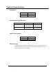
RS-422 & RS-485 (DB9 Male)
Pin # Signal Name Mode
1 RX + Receive Data Positive Input
2 RX – Receive Data Negative Input
3 TX – Transmit Data Negative Output
4 TX + Transmit Data Positive Output
5 GND Ground
6 RTS + Request to Send Positive Output
7 RTS – Request to Send Negative Output
8 CTS – Clear to Send Negative Input
9 CTS + Clear to Send Positive Input
© Sealevel Systems, Inc.
- 20 -
COMM+2.LPCIe User Manual