ULTRA 485+2.PCI USER MANUAL TM Part # 7204 Sealevel Systems, Inc P.O. Box 830 Liberty, SC 29657 USA Phone: (864) 843-4343 FAX: (864) 843-3067 www.sealevel.
Contents INTRODUCTION ........................................................................ 1 OVERVIEW ......................................................................................1 WHAT’S INCLUDED.........................................................................1 FACTORY DEFAULT SETTINGS ........................................................1 CARD SETUP ............................................................................ 2 RS-485 ENABLE MODES ..................................
APPENDIX E - SILK-SCREEN ................................................. 19 APPENDIX F - COMPLIANCE NOTICES .................................. 20 FEDERAL COMMUNICATIONS COMMISSION STATEMENT...............20 EMC DIRECTIVE STATEMENT ......................................................20 WARRANTY ............................................................................ 21 Figures Figure 1- Headers J1B and J2B, RS-422..................................................
Introduction Introduction Overview The Sealevel Systems ULTRA 485+2.PCI is a two channel PCI Bus serial I/O adapter for the PC and compatibles and features the 16850 advanced UART. It provides two field selectable RS-422/485 serial ports supporting data rates up to 460.8K bps. The 16850 advanced UART provides a 128 byte FIFO that helps reduce processor overhead by reducing the number of interrupts that need servicing. Each port can be individually configured.
Card Setup Card Setup In all cases J1x refers to settings for the first port and J2x refer to settings for the second port. RS-485 Enable Modes RS-485 is ideal for multi-drop or network environments. RS-485 requires a tri-state driver that will allow the electrical presence of the driver to be removed from the line. The driver is in a tri-state or high impedance condition when this occurs. Only one driver may be active at a time and the other driver(s) must be tri-stated.
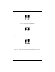
Card Setup AT RT NE Interface Mode Examples J1B – J2B AT RT NE Figure 1- Headers J1B and J2B, RS-422 AT RT NE Figure 2 - Headers J1B and J2B, RS-485 ‘Auto’ Enabled, with ‘No Echo’ Figure 3 - Headers J1B and J2B, RS-485 ‘Auto’ Enabled, with ‘Echo’ Sealevel Systems ULTRA 485+2.
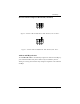
Card Setup AT RT NE Interface Mode Examples J1B and J2B (continued) AT RT NE Figure 4 - Headers J1B and J2B, RS-485 ‘RTS’ Enabled, with ‘No Echo’ Figure 5 - Headers J1B and J2B, RS-485 ‘RTS’ Enabled, with ‘Echo’ Address and IRQ selection The ULTRA 485+2.PCI is automatically assigned I/O addresses and IRQs by your motherboard BIOS. Only the I/O address may be modified by the user. Adding or removing other hardware may change the assignment of I/O addresses and IRQs. Sealevel Systems ULTRA 485+2.
Card Setup Line Termination Typically, each end of the RS-485 bus must have line terminating resistors (RS-422 terminates at the receive end only). A 120-ohm resistor is across each RS-422/485 input in addition to a 1K ohm pull-up/pull-down combination that biases the receiver inputs. Headers J1A and J2A allow the user to customize this interface to their specific requirements. Each jumper position corresponds to a specific portion of the interface. If multiple ULTRA 485+2.
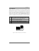
Card Setup Clock Modes The ULTRA 485+2.PCI employs a unique clocking option that allows the end user to select from divide by 4, divide by 2 and divide by 1 clocking modes. These modes are selected at Headers J1C through J4C. DIV1 DIV2 DIV4 To select the Baud rates commonly associated with COM: ports (i.e. 2400, 4800, 9600, 19.2, … 115.2K Bps ) place the jumper in the divide by 4 mode (silk-screen DIV4).
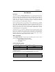
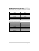
Card Setup Baud Rates and Divisors for the ‘Div1’ mode The following table shows some common data rates and the rates you should choose to match them if using the adapter in the ‘Div1’ mode. For this Data Rate 1200 bps 2400 bps 4800 bps 9600 bps 19.2K bps 57.6 K bps 115.2 K bps 230.4K bps 460.8K bps Choose this Data Rate 300 bps 600 bps 1200 bps 2400 bps 4800 bps 14.4K bps 28.8K bps 57.6 K bps 115.
Card Setup Baud Rates and Divisors for the ‘Div2’ mode The following table shows some common data rates and the rates you should choose to match them if using the adapter in the ‘Div2’ mode. For this Data Rate 1200 bps 2400 bps 4800 bps 9600 bps 19.2K bps 38.4K bps 57.6 K bps 115.2 K bps 230.4 K bps Choose this Data Rate 600 bps 1200 bps 2400bps 4800 bps 9600 bps 19.2K bps 28.8K bps 57.6 K bps 115.
Installation Installation Operating System Installation For Windows Users Start by choosing Install Software at the beginning of the CD. Choose Asynchronous COM: Port Software, SeaCOM. Other Operating Systems Refer to the appropriate section of the Serial Utilities Software.System Installation System Installation The ULTRA 485+2.PCI can be installed in any of the PCI expansion slots and contains several jumper straps for each port that must be set for proper operation. 1. 2. 3. 4. 5. 6. 7.
Technical Description Technical Description The Sealevel Systems ULTRA 485+2.PCI provides a PCI interface adapter with 2 asynchronous, field selectable, RS-422/485 serial ports for industrial automation and control applications. The ULTRA 485+2.PCI uses the 16850 advanced UART. This chip features programmable baud rates, data format, interrupt control and a 128-byte input and output FIFO.
Technical Description Why use an ISP? The answer to the polling inefficiency was the Interrupt Status Port (ISP). The ISP is a read only 8-bit register that sets a corresponding bit when an interrupt is pending. Port 1 interrupt line corresponds with Bit D0 of the status port, Port 2 with D1 etc. The use of this port means that the software designer now only has to poll a single port to determine if an interrupt is pending.
Technical Description Connector Pin Assignments RS-422/485 Signal GND TX + TXRTS+ RTSRX+ RXCTS+ CTS- Name Ground Transmit Data Positive Transmit Data Negative Request To Send Positive Request To Send Negative Receive Data Positive Receive Data Negative Clear To Send Positive Clear To Send Negative Pin # 5 4 3 6 7 1 2 9 8 Mode Output Output Output Output Input Input Input Input Technical Note: Please terminate any control signals that are not going to be used.
Specifications Specifications Environmental Specifications Specification Temperature Range Humidity Range Operating 0º to 50º C (32º to 122º F) 10 to 90% R.H. Non-Condensing Storage -20º to 70º C (-4º to 158º F) 10 to 90% R.H. Non-Condensing Manufacturing • All Sealevel Systems Printed Circuit boards are built to U. L. 94V0 rating and are 100% electrically tested. These printed circuit boards are solder mask over bare copper or solder mask over tin nickel.
Appendix A - Troubleshooting Appendix A - Troubleshooting A Serial Utility Diskette is supplied with the Sealevel Systems adapter and will be used in the troubleshooting procedures. By using this diskette and following these simple steps, most common problems can be eliminated without the need to call Technical Support. 1. Identify all I/O adapters currently installed in your system. This includes your on-board serial ports, controller cards, sound cards etc.
Appendix A - Troubleshooting PCI COM NUMBER SELECTION IN WINDOWS 95 When installing a multi-port PCI card in Windows 95 the default starting COM: number assigned to the first port will be COM:5 if no COM:5 exists. If there is a COM: 5, 6, etc., the next available COM: number will be assigned to the first port with all additional ports following in ascending order.
Appendix B - How To Get Assistance Appendix B - How To Get Assistance 1. Begin by reading through the Trouble Shooting Guide in Appendix A. If assistance is still needed please see below. 2. When calling for technical assistance, please have your user manual and current adapter settings. If possible, please have the adapter installed in a computer ready to run diagnostics. 3. Sealevel Systems provides an FAQ section on its web site. Please refer to this for many commonly asked questions.
Appendix C – Electrical Interface Appendix C - Electrical Interface RS-422 The RS-422 specification defines the electrical characteristics of balanced voltage digital interface circuits. RS-422 is a differential interface that defines voltage levels and driver/receiver electrical specifications. On a differential interface, logic levels are defined by the difference in voltage between a pair of outputs or inputs.
Appendix D - Asynchronous Communications Appendix D - Asynchronous Communications Serial data communications implies that individual bits of a character are transmitted consecutively to a receiver that assembles the bits back into a character. Data rate, error checking, handshaking, and character framing (start/stop bits) are pre-defined and must correspond at both the transmitting and receiving ends.
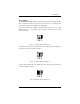
Appendix E - Silk-Screen Appendix E - Silk-Screen 5.0" 4.2" Sealevel Systems ULTRA 485+2.
Appendix F - Compliance Notices Appendix F - Compliance Notices Federal Communications Commission Statement FCC - This equipment has been tested and found to comply with the limits for Class A digital device, pursuant to Part 15 of the FCC Rules. These limits are designed to provide reasonable protection against harmful interference when the equipment is operated in a commercial environment.
Warranty Warranty Sealevel Systems, Inc. provides a limited lifetime warranty. Should this product fail to be in good working order at any time during this period, Sealevel Systems will, at it’s option, replace or repair it at no additional charge except as set forth in the following terms. This warranty does not apply to products damaged by misuse, modifications, accident or disaster.