
User guide


Technical Description
Sealevel Systems COMM+232.PCI Page 6
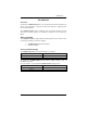
The ISP is at Base+7 on each port (Example: Base = 280 Hex, Status Port = 287,
28F… etc.). The COMM+232.PCI will allow any one of the available locations
to be read to obtain the value in the status register. Both status ports on the
COMM+232.PCI are identical, so any one can be read.
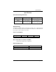
Example: This indicates that Channel 2 has an interrupt pending.
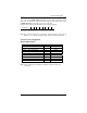
Bit Position: 7 6 5 4 3 2 1 0
Value Read: X X X X X X
1
0
Note: Bit positions D7-D2 are not biased in anyway and may report back as
either a 1 or a 0. When checking the ISP, these bits should be masked.
Connector Pin Assignments
RS-232 (DB-9 Male)
Name Pin # Mode
TD Transmit Data 3 Output
RTS Request To Send 7 Output
DTR Data Term Ready 4 Output
GND Ground 5
RD Receive Data 2 Input
DCD Data Carrier Detect 1 Input
DSR Data Set Ready 6 Input
CTS Clear To Send 8 Input
RI Ring Indicator 9 Input
Note: These assignments meet EIA/TIA/ANSI-574 DTE for DB-9 type
connectors.