ULTRA COMM+2.PCI Users Manual Part # 7201 Sealevel Systems, Inc. PO Box 830 Liberty, SC 29657 USA Telephone: 864.843.4343 Fax: 864.843.3067 www.sealevel.
Contents INTRODUCTION ........................................................................................................................ 1 OVERVIEW .............................................................................................................................................. 1 WHAT’S INCLUDED ................................................................................................................................. 1 FACTORY DEFAULT SETTINGS ........................................
WARRANTY ............................................................................................................................ 20 Figures Figure 1- Headers J1B and J2B, RS-422 .......................................................................................................... 2 Figure 2 - Headers J1B and J2B, RS-485 ‘Auto’ Enabled, with ‘No Echo’ .................................................. 2 Figure 3 - Headers J1B and J2B, RS-485 ‘Auto’ Enabled, with ‘Echo’ .............................
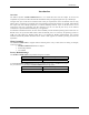
Introduction Introduction Overview The Sealevel Systems ULTRA-COMM+2.PCI is a two channel PCI Bus serial I/O adapter for the PC and compatibles. It provides two field selectable RS-232/422/485 serial ports supporting data rates up to 460.8K bps. Configure both ports as RS-232 for standard serial COM: port requirements. Choose the RS-422 mode for long distance device connections up to 4000ft. where noise immunity and high data integrity are essential.
Card Setup Card Setup In all cases J1x refers to settings for the first port and J2x refer to settings for the second port. RS-485 Enable Modes RS-485 is ideal for multi-drop or network environments. RS-485 requires a tri-state driver that will allow the electrical presence of the driver to be removed from the line. The driver is in a tri-state or high impedance condition when this occurs. Only one driver may be active at a time and the other driver(s) must be tri-stated.
AT RT NE Card Setup AT RT NE Figure 3 - Headers J1B and J2B, RS-485 ‘Auto’ Enabled, with ‘Echo’ AT RT NE Figure 4 - Headers J1B and J2B, RS-485 ‘RTS’ Enabled, with ‘No Echo’ Figure 5 - Headers J1B and J2B, RS-485 ‘RTS’ Enabled, with ‘Echo’ Address and IRQ selection The ULTRA COMM+2.PCI is automatically assigned I/O addresses and IRQs by your motherboard BIOS. Only the I/O address may be modified by the user. Adding or removing other hardware may change the assignment of I/O addresses and IRQs.
Card Setup Line Termination Typically, each end of the RS-485 bus must have line terminating resistors (RS-422 terminates at the receive end only). A 120-ohm resistor is across each RS-422/485 input in addition to a 1K ohm pull-up/pull-down combination that biases the receiver inputs. Headers J1A and J2A allow the user to customize this interface to their specific requirements. Each jumper position corresponds to a specific portion of the interface. If multiple ULTRA COMM+2.
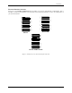
Card Setup Electrical Interface Selection RS-422 E2 RS-422 E2 RS-232 E3 RS-232 E3 E4 RS-422 E4 Port 2 Port 2 Port 1 RS-232 E1 Port 1 RS-232 E1 RS-422 Each port on the ULTRA COMM+2.PCI has the ability to be used in either RS-232 or RS-422/485. This is selectable via four 24 pin DIP-shunts at E1-E4. Please use the following illustration to aid in the configuration of your electrical interface.
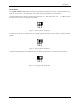
Card Setup Clock Modes The ULTRA COMM+2.PCI employs a unique clocking option that allows the end user to select from divide by 4, divide by 2 and divide by 1 clocking modes. These modes are selected at Headers J1C through J4C. DIV1 DIV2 DIV4 To select the Baud rates commonly associated with COM: ports (i.e. 2400, 4800, 9600, 19.2, … 115.2K Bps ) place the jumper in the divide by 4 mode (silk-screen DIV4).
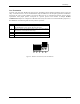
Card Setup Baud Rates and Divisors for the ‘Div1’ mode The following table shows some common data rates and the rates you should choose to match them if using the adapter in the ‘Div1’ mode. For this Data Rate 1200 bps 2400 bps 4800 bps 9600 bps 19.2K bps 57.6 K bps 115.2 K bps 230.4K bps 460.8K bps Choose this Data Rate 300 bps 600 bps 1200 bps 2400 bps 4800 bps 14.4K bps 28.8K bps 57.6 K bps 115.
Card Setup Baud Rates and Divisors for the ‘Div2’ mode The following table shows some common data rates and the rates you should choose to match them if using the adapter in the ‘Div2’ mode. For this Data Rate 1200 bps 2400 bps 4800 bps 9600 bps 19.2K bps 38.4K bps 57.6 K bps 115.2 K bps 230.4 K bps Choose this Data Rate 600 bps 1200 bps 2400bps 4800 bps 9600 bps 19.2K bps 28.8K bps 57.6 K bps 115.
Installation Installation Operating System Installation Windows 95/98/ME/NT/2000/XP Do not install the Adapter in the machine until the software has been fully installed. 1. Start Windows. 2. Insert the Sealevel Systems CD in to your CD drive. 3. If ‘Auto-Start’ is enabled for this drive the software will automatically launch. Otherwise, point your browser to the ‘Index.htm’ on the root directory of the CD 4. Select ‘Install Software’. 5. Select the Part Number for your adapter from the listing.
Installation Physical Installation The adapter can be installed in any 5V PCI expansion slot and contains several jumper straps for each port that must be set for proper. Do not install the Adapter in the machine until the software has been fully installed. 1. Turn off PC power. Disconnect the power cord. 2. Remove the PC case cover. 3. Locate an available PCI slot and remove the blank metal slot cover. 4. Gently insert the PCI adapter into the slot. Make sure that the adapter is seated properly.
Technical Description Technical Description The Sealevel Systems ULTRA COMM+2.PCI provides a PCI interface adapter with 2 asynchronous serial ports providing a versatile interface, field selectable as RS-232 for modems, printers and plotters, as well as RS-422/485 for industrial automation and control applications. The ULTRA COMM+2.PCI utilizes the 16550 UART. This chip features programmable baud rates, data format, interrupt control and a 16-byte input and output FIFO.
Technical Description Connector Pin Assignments RS-232 (DB-9 Male) Signal TD RTS DTR GND RD DCD DSR CTS RI Name Transmit Data Request To Send Data Term Ready Ground Receive Data Data Carrier Detect Data Set Ready Clear To Send Ring Indicator Pin # 3 7 4 5 2 1 6 8 9 Mode Output Output Output Input Input Input Input Input Note: These assignments meet EIA/TIA/ANSI-574 DTE for DB-9 type connectors. Technical Note: Please terminate any control signals that are not going to be used.
Specifications Specifications Environmental Specifications Specification Temperature Range Humidity Range Operating 0º to 70º C (32º to 158º F) 10 to 90% R.H. Non-Condensing Storage -50º to 105º C (-58º to 221º F) 10 to 90% R.H. Non-Condensing Manufacturing All Sealevel Systems Printed Circuit boards are built to UL 94V0 rating and are 100% electrically tested. These printed circuit boards are solder mask over bare copper or solder mask over tin nickel.
Appendix A - Troubleshooting Appendix A - Troubleshooting Sealevel Software is supplied with the Sealevel Systems adapter and may be used in the troubleshooting procedures. Using this software and following these simple steps can eliminate most common problems without the need to call Technical Support. 1. Identify all I/O adapters currently installed in your system. This includes your on-board serial ports, controller cards, sound cards etc.
Appendix B - How To Get Assistance Appendix B - How To Get Assistance Please refer to Troubleshooting Guide prior to calling Technical Support. 1. Begin by reading through the Trouble Shooting Guide in Appendix A. If assistance is still needed please see below. 2. When calling for technical assistance, please have your user manual and current adapter settings. If possible, please have the adapter installed in a computer ready to run diagnostics. 3.
Appendix C – Electrical Interface Appendix C - Electrical Interface RS-232 Quite possibly the most widely used communication standard is RS-232. This implementation has been defined and revised several times and is often referred to as RS-232 or EIA/TIA-232. The IBM PC computer defined the RS-232 port on a 9 pin D sub connector and subsequently the EIA/TIA approved this implementation as the EIA/TIA-574 standard.
Appendix D - Asynchronous Communications Appendix D - Asynchronous Communications Serial data communications implies that individual bits of a character are transmitted consecutively to a receiver that assembles the bits back into a character. Data rate, error checking, handshaking, and character framing (start/stop bits) are pre-defined and must correspond at both the transmitting and receiving ends.
Appendix E - Silk-Screen Appendix E - Silk-Screen 5.0" 4.2" Sealevel Systems ULTRA COMM+2.
Appendix F - Compliance Notices Appendix F - Compliance Notices Federal Communications Commission Statement FCC - This equipment has been tested and found to comply with the limits for Class A digital device, pursuant to Part 15 of the FCC Rules. These limits are designed to provide reasonable protection against harmful interference when the equipment is operated in a commercial environment.
Warranty Warranty Sealevel's commitment to providing the best I/O solutions is reflected in the Lifetime Warranty that is standard on all Sealevel manufactured products. We are able to offer this warranty due to our control of manufacturing quality and the historically high reliability of our products in the field. Sealevel products are designed and manufactured at its Liberty, South Carolina facility, allowing direct control over product development, production, burn-in and testing. Sealevel Systems, Inc.