ULTRA COMM+I.LPCI Users Manual Part # 7108 Sealevel Systems, Inc. PO Box 830 Liberty, SC 29657 USA Telephone: 864.843.4343 Fax: 864.843.3067 www.sealevel.
Contents INTRODUCTION ........................................................................................................................ 1 OVERVIEW .............................................................................................................................................. 1 WHAT’S INCLUDED ................................................................................................................................. 1 CARD SETUP .....................................................
Introduction Introduction Overview The Sealevel Systems ULTRA COMM+I.LPCI is a single channel isolated low profile Universal Bus serial I/O adapter for the PC and compatibles. Utilizing the Exar 16C850 UART with its industry leading 128 byte FIFOs, it provides a field selectable RS-232/422/485 serial port supporting data rates up to 921.6K bps (RS-422/485). Configure as RS-232 for standard serial COM: port requirements. Choose the RS-422 mode for long distance device connections up to 5000ft.
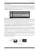
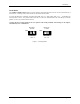
Card Setup Card Setup Electrical Interface Selection The ULTRA COMM+I.LPCI has the ability to be used as RS-232, RS-422 or RS-485. This is selectable via DIP-switch SW1. Please use the following examples to configure your adapter.
Card Setup Line Termination Typically, each end of the RS-485 bus must have line-terminating resistors (RS-422 terminates at the receive end only). A 120-ohm resistor is across each RS-422/485 input in addition to a 1K-ohm pull-up/pull-down combination that biases the receiver inputs. Switches SW1 and SW2 allow the user to customize this interface to their specific requirements. Each switch position corresponds to a specific portion of the interface. If multiple ULTRA COMM+I.
Card Setup Clock Modes The ULTRA COMM+I.LPCI employs a unique clocking option that allows the end user to select from divide by 4 and divide by 1 clocking modes. These modes are selected at switches SW-2. To select the Baud rates commonly associated with COM: ports (i.e. 2400, 4800, 9600, 19.2, … 115.2K Bps) set switch position 2 to the ‘On’ position (silk-screen D4). To select the maximum data rate (921.6K bps) set switch position 1 to the ‘On’ position (silk-screen D1).
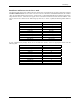
Card Setup Baud Rates and Divisors for the ‘Div1’ mode The following table shows some common data rates and the rates you should choose to achieve them when using the ULTRA COMM+I.LPCI in the D1 mode. If the O/S of choice is Windows 95/98/ME/2000/NT/XP, the oscillator value (14.7456 MHz) should entered into the ‘Advanced Tab’ on 95/98/Me/2000/XP Device Manager applet.
Installation Installation Operating System Installation Windows 95/98/ME/NT/2000/XP Do not install the Adapter in the machine until the software has been fully installed. 1. Start Windows. 2. Insert the Sealevel Systems CD in to your CD drive. 3. If ‘Auto-Start’ is enabled for this drive the software will automatically launch. Otherwise, point your browser to the ‘Index.htm’ on the root directory of the CD 4. Select ‘Install Software’. 5. Select the Part Number for your adapter from the listing.
Installation Physical Installation The adapter can be installed in any PCI (5V or 3.3 V) expansion slot. Do not install the Adapter in the machine until the software has been fully installed. 1. Turn off PC power. Disconnect the power cord. 2. Remove the PC case cover. 3. Locate an available PCI slot and remove the blank metal slot cover. 4. Gently insert the PCI adapter into the slot. Make sure that the adapter is seated properly. 5. Replace the screw.
Technical Description Technical Description The Sealevel Systems ULTRA COMM+I.LPCI provides a PCI interface adapter with an isolated asynchronous serial port providing a versatile interface, field selectable as RS-232 for modems, printers and plotters, as well as RS-422/485 for industrial automation and control applications. Isolation is important in installations where the equipment being connected to the PC is either far from the PC, or on a different power transformer circuit.
Specifications Specifications Environmental Specifications Specification Temperature Range Humidity Range Operating 0º to 70º C (32º to 158º F) 10 to 90% R.H. Non-Condensing Storage -50º to 105º C (-58º to 221º F) 10 to 90% R.H. Non-Condensing Manufacturing All Sealevel Systems Printed Circuit boards are built to UL 94V0 rating and are 100% electrically tested. These printed circuit boards are solder mask over bare copper or solder mask over tin nickel.
Appendix A - Troubleshooting Appendix A - Troubleshooting Sealevel Software is supplied with the Sealevel Systems adapter and may be used in the troubleshooting procedures. Using this software and following these simple steps can eliminate most common problems without the need to call Technical Support. 1. Identify all I/O adapters currently installed in your system. This includes your on-board serial ports, controller cards, sound cards etc.
Appendix B - How To Get Assistance Appendix B - How To Get Assistance Please refer to Troubleshooting Guide prior to calling Technical Support. 1. Begin by reading through the Trouble Shooting Guide in Appendix A. If assistance is still needed please see below. 2. When calling for technical assistance, please have your user manual and current adapter settings. If possible, please have the adapter installed in a computer ready to run diagnostics. 3.
Appendix C – Electrical Interface Appendix C - Electrical Interface RS-232 Quite possibly the most widely used communication standard is RS-232. This implementation has been defined and revised several times and is often referred to as RS-232 or EIA/TIA-232. The IBM PC computer defined the RS-232 port on a 9 pin D sub connector and subsequently the EIA/TIA approved this implementation as the EIA/TIA-574 standard.
Appendix D - Ground Loop Phenomenon Appendix D - Ground Loop Phenomenon What is Ground Loop? Ground loop Phenomenon occurs when two (or more) pieces of equipment are connected together with a common ground and a different ground potential exists at each location. This current can cause the connected equipment to experience noise that in turn causes data transmission errors. In the extreme this ground current can cause equipment malfunction or even destruction.
Appendix E - Asynchronous Communications Appendix E - Asynchronous Communications Serial data communications implies that individual bits of a character are transmitted consecutively to a receiver that assembles the bits back into a character. Data rate, error checking, handshaking, and character framing (start/stop bits) are pre-defined and must correspond at both the transmitting and receiving ends.
Appendix F - Silk-Screen Appendix F - Silk-Screen 2.536" 4.721" Sealevel Systems ULTRA COMM+I.
Appendix G - Compliance Notices Appendix G - Compliance Notices Federal Communications Commission Statement FCC - This equipment has been tested and found to comply with the limits for Class A digital device, pursuant to Part 15 of the FCC Rules. These limits are designed to provide reasonable protection against harmful interference when the equipment is operated in a commercial environment.
Warranty Warranty Sealevel's commitment to providing the best I/O solutions is reflected in the Lifetime Warranty that is standard on all Sealevel manufactured products. We are able to offer this warranty due to our control of manufacturing quality and the historically high reliability of our products in the field. Sealevel products are designed and manufactured at its Liberty, South Carolina facility, allowing direct control over product development, production, burn-in and testing. Sealevel Systems, Inc.