
User Manual


© Sealevel Systems, Inc. - 3 -
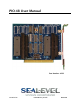
PIO-48 User Manual
For high-current, high-voltage applications:
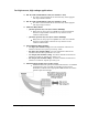
IDC 50 to IDC 50 Pin Ribbon Cable (Part Number CA167)
− 40” cable connects the PIO-48 to solid-state relay racks equipped
with 50-pin header interface.
IDC 50 to IDC 50 Pin Ribbon Cable (Part Number CA135)
− 40” cable connects the PIO-48 to solid-state relay racks equipped
with 50-pin edge connector.
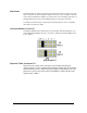
Solid-State Relay Racks:
• Quad six position relay rack (Part Number PB24HQ)
− Relay rack can accept up to six QSSRs for a total of 24 channels.
Features a 50-pin header connector for easy interface via 50-
conductor ribbon cables.
• Quad four position relay rack (Part Number PB16HQ)
− Relay rack can accept up to four QSSRs for a total of 16 channels.
Features a 50-pin header connector for easy interface via 50-
conductor ribbon cables.
Quad Solid-State Relay Modules:
• AC Input (Part Number IA5Q) - Provides 4 channels of discrete I/O
interface to monitor AC inputs up to 140V @ 10mA.
• DC Input (Part Number IB5Q) - Provides 4 channels of discrete I/O
interface to monitor DC inputs from 3.3V to 32V.
• AC Output (Part Number OA5Q) - Provides 4 channels of discrete I/O
interface to control AC outputs up to 140V @ 3A.
• DC Output (Part Number OB5Q) - Provides 4 channels of discrete I/O
interface to control DC outputs up to 60V @ 3A.
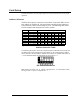
Simulation/debug module (Part Number TA01)
− Module simulates the operation and load characteristics of a standard
24-channel relay rack. An LED corresponding to each port bit
illuminates to indicate state. Eight position DIP-switches are used to
generate input status changes.