
User Manual


© Sealevel Systems, Inc. - 12 -
PIO-48 User Manual
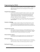
I/O Control Word
Each port may be configured as either Input or Output. This is accomplished by
writing the correct Control Word (CW) to the proper register.
Control Word (X = 0) Hex Value Port Setup
7 6 5 4 3 2 1 0
A B C
1 X X 0 0 X 0 0 80 Out Out Out
1 X X 0 0 X 0 1 81 Out Out In
1 X X 0 0 X 1 0 82 Out In Out
1 X X 0 0 X 1 1 83 Out In In
1 X X 0 1 X 0 0 88 Out Out In
1 X X 0 1 X 0 1 89 Out Out In
1 X X 0 1 X 1 0 8A Out In In
1 X X 0 1 X 1 1 8B Out In In
1 X X 1 0 X 0 0 90 In Out Out
1 X X 1 0 X 0 1 91 In Out In
1 X X 1 0 X 1 0 92 In In Out
1 X X 1 0 X 1 1 93 In In In
1 X X 1 1 X 0 0 98 In Out In
1 X X 1 1 X 0 1 99 In Out In
1 X X 1 1 X 1 0 9A In In In
1 X X 1 1 X 1 1 9B In In In
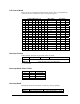
Interrupt Control
When enabled, interrupts are generated on Port A bit D0.
IRQENn
Interrupt enable 1 = enabled 0 = disabled ( 0 on power up )
IRQCn0
IRQCn1
Interrupt mode select, see table below
Interrupt mode select, see table below
n = port number
Interrupt Mode Select Table
IRQCn1 IRQCn0 INT Type
0 0 Low level
0 1 High level
1 0 Falling edge
1 1 Rising edge
Interrupt Read
Reading the INTSTAT port (Base+5) clears any interrupt pending.
IRQST1 (D0) Interrupt status 1 = interrupt pending, 0 = none
IRQST2 (D1) Interrupt status 1 = interrupt pending, 0 = none