
User guide


Technical Description
Sealevel Systems PC-ACB.MP Page 4
Interface Selection
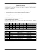
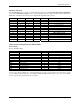
The PC-ACB.MP supports a variety of electrical interfaces. Refer to the Control and Status Register Definitions
found in the Technical Description section of this manual for this bit description. There is line termination on
RXD, RXC, and TXC in the following modes: RS-530, RS-530A, RS-485T, and V.35.
HEX M3 M2 M1 M0 Interface Mode
0 0 0 0 0
All signals are high impedance
1 0 0 0 1 * not supported *
2 0 0 1 0
RS-232
3 0 0 1 1 * not supported *
4 0 1 0 0
RS-485T with 120 ohm termination
5 0 1 0 1
RS-485 without termination
6,7,8,9 0 1 1 0 * not supported *
A 1 0 1 0
single ended loop-back
B 1 0 1 1
differential loop-back
C 1 1 0 0 * not supported *
D 1 1 0 1
RS-530
E 1 1 1 0
V.35
F 1 1 1 1
RS-530A
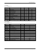
25 Pin Connector Signal Layouts (DB-25 Male)
RS-232 Signals
Base+5, M3-M0=2, 0010
Signal Name Pin # Mode
GND Ground 7
RD Receive Data 3 Input
CTS Clear To Send 5 Input
DSR Data Set Ready 6 Input
DCD Data Carrier Detect 8 Input
TM Test Mode 25 Input
TXC Transmit Clock 15 Input
RXC Receive Clock 17 Input
TSET Transmit Signal Element Timing 24 Output
DTR Data Terminal Ready 20 Output
TD Transmit Data 2 Output
RTS Request To Send 4 Output
Technical Note: Please terminate any control signals that are not going to be used. The most common way to do this
is connect RTS to CTS and RI. Also, connect DCD to DTR and DSR. Terminating these pins, if not used, will help
insure you get the best performance from your adapter.