PC-ACB.MP USER MANUAL TM Part # 3612 Sealevel Systems, Inc P.O. Box 830 Liberty, SC 29657 USA Phone: (864) 843-4343 FAX: (864) 843-3067 www.sealevel.
Contents INTRODUCTION .............................................................................................................................1 OVERVIEW ................................................................................................................................................... 1 WHAT’S INCLUDED ...................................................................................................................................... 1 INSTALLATION .....................................
Introduction Introduction Overview In the last few years, the portable and notebook market has grown by leaps and bounds. Most early laptops and notebooks handled I/O expansion through proprietary expansion slots. These slots provided limited expansion for specific peripherals such as modems and FAX peripherals. Mass storage peripherals were factory installed and could not be easily changed.
Installation Installation Card and Socket Services must be loaded on the system prior to installing the PC-ACB.MP card. Card and Socket Services are supplied by the PCMCIA slot provider (i.e. the computer manufacturer or the PC adapter manufacturer). These may be in the form of a third party add-on Card and Socket service (e.g. CardSoft’s CardWizard) or with your current operating system (e.g. Windows 95/98/NT/2000). Socket Services are the lowest level of the PCMCIA Software hierarchy.
Technical Description Technical Description The PC-ACB.MP utilizes the Zilog 85233 Enhanced Serial Communications Controller (ESCC). This chip features programmable baud rate, data format and interrupt control. Refer to the ESCC Users Manual for details on programming the 85233 ESCC chip. Features • One channel of synchronous or asynchronous communications using the Zilog Z85233 chip • Programmable electrical interface selection EIA/TIA-232/530/530A/485 and ITU V.
Technical Description Interface Selection The PC-ACB.MP supports a variety of electrical interfaces. Refer to the Control and Status Register Definitions found in the Technical Description section of this manual for this bit description. There is line termination on RXD, RXC, and TXC in the following modes: RS-530, RS-530A, RS-485T, and V.35.
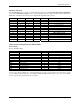
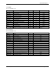
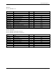
Technical Description V.
Technical Description RS-530A Base+5, M3-M0=F, 1111 Signal GND RDB RX+ RDA RXCTSA CTSDCDA DCDTXCB TXC+ TXCA TXCRXCB RXC+ RXCA RXCTDB TX+ TDA TXRTSA RTSDTRA DTRTSETB TSET+ TSETA TSET- Name Ground Receive Positive Receive Negative Clear To Send Negative Data Carrier Detect Negative Transmit Clock Positive Transmit Clock Negative Receive Clock Positive Receive Clock Negative Transmit Positive Transmit Negative Request To Send Negative Data Terminal Ready Negative Transmit Signal Element Timing Positive Trans
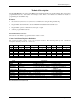
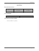
Specifications Specifications Environmental Specifications Specification Temperature Range Humidity Range Operating 0 to 50 º C (32 to 122 º F) 10 - 90% R.H. Non Condensing Storage -20 to 70 º C (-4 to 158 ºF) 10 - 90% R.H. Non Condensing Power Consumption Supply line Rating +5 VDC 170 mA Mean Time Between Failures (MTBF) Greater than 150,000 hours. (Calculated) Sealevel Systems PC-ACB.
Appendix A - Troubleshooting Appendix A - Troubleshooting The Developers Toolkit Software is supplied with the Sealevel Systems adapter and will be used in the troubleshooting procedures. Using this software and following these simple steps can eliminate most common problems without the need to call Technical Support. 1. Identify all I/O adapters currently installed in your system. This includes your on-board serial ports, controller cards, sound cards etc.
Appendix B - How To Get Assistance Appendix B - How To Get Assistance Please refer to Troubleshooting Guide prior to calling Technical Support. 1. Begin by reading through the Trouble Shooting Guide in Appendix A. If assistance is still needed please see below. 2. When calling for technical assistance, please have your user manual and current adapter settings. If possible, please have the adapter installed in a computer ready to run diagnostics. 3.
Appendix C - Electrical Interface Appendix C - Electrical Interface RS-232 Quite possibly the most widely used communication standard is RS-232. This implementation has been defined and revised several times and is often referred to as RS-232 or EIA/TIA-232. It is defined by the EIA as the Interface between Data Terminal Equipment and Data Circuit- Terminating Equipment Employing Serial Binary Data Interchange. The mechanical implementation of RS-232 is on a 25 pin D sub connector.
Appendix C - Electrical Interface V.35 V.35 is a standard defined by ITU (formerly CCITT) that specifies an electrical, mechanical, and physical interface that is used extensively by high-speed digital carriers such as AT&T Dataphone Digital Service (DDS). ITU V.35 is an international standard that is often refereed to as Data Transmission at 48 Kbps Using 60 - 108 KHz Group-Band Circuits. ITU V.35 electrical characteristics are a combination of unbalanced voltage and balanced current mode signals.
Appendix D – Compliance Notices Appendix D - Compliance Notices Federal Communications Commission Statement FCC - This equipment has been tested and found to comply with the limits for Class A digital device, pursuant to Part 15 of the FCC Rules. These limits are designed to provide reasonable protection against harmful interference when the equipment is operated in a commercial environment.
Warranty Warranty Sealevel Systems, Inc. provides a limited lifetime warranty. Should this product fail to be in good working order at any time during this period, Sealevel Systems will, at it’s option, replace or repair it at no additional charge except as set forth in the following terms. This warranty does not apply to products damaged by misuse, modifications, accident or disaster.