ULTRA COMM+422™ USER MANUAL Part #3055 Sealevel Systems, Inc. PO Box 830 Liberty, SC 29657 USA Telephone: (864) 843-4343 Fax: (864) 843-3067 www.sealevel.
Contents INTRODUCTION ........................................................................ 1 OVERVIEW......................................................................................1 WHAT’S INCLUDED ........................................................................1 FACTORY DEFAULT SETTINGS ........................................................1 CARD SETUP ............................................................................ 2 ADDRESS SELECTION......................................
APPENDIX D - ASYNCHRONOUS COMMUNICATIONS ............ 23 APPENDIX E - SILK-SCREEN ................................................. 24 APPENDIX F - COMPLIANCE NOTICES .................................. 25 FEDERAL COMMUNICATIONS COMMISSION STATEMENT ..............25 EMC DIRECTIVE STATEMENT ......................................................25 WARRANTY ............................................................................ 26 Figures Figure 1 - Available Address Combinations ........................
Introduction Introduction Overview The Sealevel Systems ULTRA COMM+422 provides the PC with four additional RS-422/485 serial ports for terminals, modems, printers, etc. The unique feature of the ULTRA COMM+422 is the ability to be RS-485 compatible without the need for special software or drivers. This ability is especially useful in Windows, Windows NT, and OS/2 environments where the lower level I/O control is abstracted from the application program.
Card Setup Card Setup The ULTRA COMM+422 contains several jumper straps, which must be set for proper operation. Address Selection Each port on the ULTRA COMM+422 occupies eight consecutive I/O locations. A DIP-switch is used to set the base address for these locations.
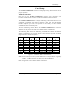
Card Setup The second mode of address selection provides the compatibility mode. In this mode the DIP-switch sets the base address and the adapter occupies 32 consecutive I/O locations. The following table illustrates the location of each port and its relationship to the other ports. Note: For switches 1 - 5 to become active, switches 6, 7 & 8 must be set in the ‘On’ or ‘Up’ position.
Card Setup Jumper Selections For ease of configuration, the headers are grouped by port. Port one headers have a ‘J1’ prefix; Port two headers have the ‘J2’ prefix, etc. For example, the header that controls the Port one IRQ selection is J1B; the header that controls the Port 2 IRQ selection is J2B. The silk-screen also provides information for configuring the adapter without the use of the manual. This is particularly useful in field re-configuration.
Card Setup Interrupt Modes Headers J1A through J4A select the interrupt modes for each port. Each port must be set in the correct mode to insure proper operation. ‘N’ indicates the (N)ormal, single interrupt per port mode. ‘S’ Indicates the (S)hared interrupt mode, which allows more than one port to access a single IRQ. ‘M’ indicates the inclusion of a 1K ohm pull-down resistor required on one port when sharing interrupts.
Card Setup RS-485 Enable Modes RS-485 is ideal for multi-drop or network environments. RS-485 requires a tri-state driver (not dual-state) that will allow the electrical presence of the driver to be removed from the line. The driver is in a tri-state or high impedance condition when this occurs. Only one driver may be active at a time and the other driver(s) must be tri-stated. The output modem control signal Request To Send (RTS) is typically used to control the state of the driver.
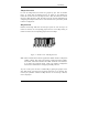
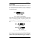
Card Setup AT RT NE Interface Mode Examples J1D – J4D AT RT NE Figure 6- Headers J1D- J4D, RS-422 AT RT NE Figure 7 - Headers J1D- J4D, RS-485 ‘Auto’ Enabled, with ‘No Echo’ Figure 8 - Headers J1D- J4D, RS-485 ‘Auto’ Enabled, with ‘Echo’ Sealevel Systems ULTRA COMM+422 Page 7
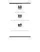
Card Setup AT RT NE Interface Mode Examples J1D – J4D (continued) AT RT NE Figure 9 - Headers J1D- J4D, RS-485 ‘RTS’ Enabled, with ‘No Echo’ Figure 10 - Headers J1D- J4D, RS-485 ‘RTS’ Enabled, with ‘Echo’ Sealevel Systems ULTRA COMM+422 Page 8
Card Setup Line Termination Typically, each end of the RS-485 bus must have line terminating resistors (RS-422 terminates at the receive end only). A 120-ohm resistor is across each RS-530/422/485 input in addition to a 1K ohm pull-up/pull-down combination that bias the receiver inputs. Headers J1E through J4E allow the user to customize this interface to their specific requirements. Each jumper position corresponds to a specific portion of the interface.
Card Setup Clock Modes The ULTRA COMM+422 employs a unique clocking option that allows the end user to select from divide by 4, divide by 2 and divide by 1 clocking modes. These modes are selected at Headers J1C through J4C. DIV1 DIV2 DIV4 To select the Baud rates commonly associated with COM: ports (i.e. 2400, 4800, 9600, 19.2, … 115.2K Bps ) place the jumper in the divide by 4 mode (silk-screen DIV4).
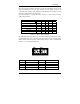
Card Setup Baud Rates and Divisors for the ‘Div1’ mode The following table shows some common data rates and the rates you should choose to match them if using the adapter in the ‘Div1’ mode. For this Data Rate 1200 bps 2400 bps 4800 bps 9600 bps 19.2K bps 57.6 K bps 115.2 K bps 230.4K bps 460.8K bps Choose this Data Rate 300 bps 600 bps 1200 bps 2400 bps 4800 bps 14.4K bps 28.8K bps 57.6 K bps 115.
Card Setup Baud Rates and Divisors for the ‘Div2’ mode The following table shows some common data rates and the rates you should choose to match them if using the adapter in the ‘Div2’ mode. For this Data Rate 1200 bps 2400 bps 4800 bps 9600 bps 19.2K bps 38.4K bps 57.6 K bps 115.2 K bps 230.4 K bps Choose this Data Rate 600 bps 1200 bps 2400bps 4800 bps 9600 bps 19.2K bps 28.8K bps 57.6 K bps 115.
Installation Installation The ULTRA COMM+422 can be installed in any of the PC expansion slots. The ULTRA COMM+422 contains several jumper straps for each port that must be set for proper operation. 1. 2. 3. 4. 5. 6. 7. 8. Turn off PC power. Disconnect the power cord. Remove the PC case cover. Locate an available slot and remove the blank metal slot cover. Gently insert the ULTRA COMM+422 into the slot. Make sure that the adapter is seated properly. Replace the screw.
Technical Description Technical Description The ULTRA COMM+422 utilizes the 16550 UART. This chip features programmable baud rates, data format, interrupt control and a 16-byte input and output FIFO. Also available as options are the Startech 16C650 and the Texas Instruments 16C750 UARTs, that provide deeper FIFOs (32 bytes) and enhanced clocking features. A second version of the ULTRA COMM+422, p/n 3441 is available without the auto enable feature for a reduced price.
Technical Description Interrupts A good description of an interrupt and it’s importance to the IBM PC can be found in the book ‘Peter Norton’s Inside the PC, Premier Edition’: “ One of the key things that makes a computer different from any other kind of man-made machine is that computers have the capability to respond to the unpredictable variety of work that comes to them. The key to this capability is a feature known as interrupts.
Technical Description Why use an ISP? The answer to the polling inefficiency was the Interrupt Status Port (ISP). The ISP is a read only 8-bit register that sets a corresponding bit when an interrupt is pending. Port 1 interrupt line corresponds with Bit D0 of the status port, Port 2 with D1 etc. The use of this port means that the software designer now only has to poll a single port to determine if an interrupt is pending.
Technical Description Connector Pin Assignments DB-9 Pin Assignments Signal GND TX + TXRTS+ RTSRX+ RXCTS+ CTS- Name Ground Transmit Data Positive Transmit Data Negative Request To Send Positive Request To Send Negative Receive Data Positive Receive Data Negative Clear To Send Positive Clear To Send Negative Pin # 5 4 3 6 7 1 2 9 8 Mode Output Output Output Output Input Input Input Input DB-37 Connector Pin Assignments Port # GND TXRTSTX+ RXCTSRTS+ RX+ CTS+ 1 33 35 17 34 36 16 18 37 15 2 14 12 30 13 1
Specifications Specifications Environmental Specifications Specification Temperature Range Humidity Range Operating 0º to 50º C (32º to 122º F) 10 to 90% R.H. Non-Condensing Storage -20º to 70º C (-4º to 158º F) 10 to 90% R.H. Non-Condensing Manufacturing • IPC 610-A Class-III standards are adhered to with a 0.1 visual A.Q.L. and 100% Functional Testing. • All Sealevel Systems Printed Circuit boards are built to U.L. 94V0 rating and are 100% electrically tested.
Appendix A - Troubleshooting Appendix A - Troubleshooting A Serial Utility Diskette is supplied with the Sealevel Systems adapter and will be used in the troubleshooting procedures. By using this diskette and following these simple steps, most common problems can be eliminated without the need to call Technical Support. 1. Identify all I/O adapters currently installed in your system. This includes your on-board serial ports, controller cards, sound cards etc.
Appendix A - Troubleshooting 8. The following are known I/O conflicts: • • • • • • 9. The 278 and 378 settings may conflict with your printer I/O adapter. 3B0 cannot be used if a Monochrome adapter is installed. 3F8-3FF is typically reserved for COM1: 2F8-2FF is typically reserved for COM2: 3E8-3EF is typically reserved for COM3: 2E8-2EF is typically reserved for COM4: Please refer to your included diskette for any post production manual updates and application specific information. 10.
Appendix B – How To Get Assistance Appendix B - How To Get Assistance Please refer to Troubleshooting Guide prior to calling Technical Support. 1. Begin by reading through the Trouble Shooting Guide in Appendix A. If assistance is still needed please see below. 2. When calling for technical assistance, please have your user manual and current adapter settings. If possible, please have the adapter installed in a computer ready to run diagnostics. 3.
Appendix C - Electrical Interface Appendix C - Electrical Interface RS-422 The RS-422 specification defines the electrical characteristics of balanced voltage digital interface circuits. RS-422 is a differential interface that defines voltage levels and driver/receiver electrical specifications. On a differential interface, logic levels are defined by the difference in voltage between a pair of outputs or inputs.
Appendix D - Asynchronous Communications Appendix D - Asynchronous Communications Serial data communications implies that individual bits of a character are transmitted consecutively to a receiver that assembles the bits back into a character. Data rate, error checking, handshaking, and character framing (start/stop bits) are pre-defined and must correspond at both the transmitting and receiving ends.
Appendix E - Silk-Screen Appendix E - Silk-Screen 4.2" 8.0" 3.
Appendix F - Compliance Notices Appendix F - Compliance Notices Federal Communications Commission Statement FCC - This equipment has been tested and found to comply with the limits for Class A digital device, pursuant to Part 15 of the FCC Rules. These limits are designed to provide reasonable protection against harmful interference when the equipment is operated in a commercial environment.
Warranty Warranty Sealevel Systems, Inc. provides a limited lifetime warranty. Should this product fail to be in good working order at any time during this period, Sealevel Systems will, at it’s option, replace or repair it at no additional charge except as set forth in the following terms. This warranty does not apply to products damaged by misuse, modifications, accident or disaster.